diy solar

diy solar

Connecting 24v Inverter directly from dc-dc booster

azree

New Member
Joined
Dec 6, 2019
Messages
14
Hi, I was wondering if i put my setup this way

2 x 100w mono panel in parallel
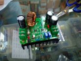
Connected to DC-DC Boost converter to output 24v DC (with constant voltage output)

Then directly supplying my 24v 500w DC-AC inverter without battery to run my electric bike charger adaptor which is 240v

This system is to charge my 48v 11Ah lithium battery. The charger adaptor is rated 240v AC input and output 55V 4A DC

Is it possible?
Thanks in advance
 
I doubt anyone can answer that directly, the problem being the panels probably supply 0 to 220W or so (depending on sun angle, temperature, & time of day), but the charger is rated at 220W (55V x 4 A). It's possible the charger just won't kick on (e.g., won't work) or that it'll pass through what it gets (e.g., it would work). Ditto the inverter.

But why go through that? It would probably be more efficient to skip the inverter and 240V charger by charging the battery directly from the booster. That might depend on how stable your booster is. Depending on panel voltage, you might also do better with them in series. You might also need a blocking diode so the battery doesn't discharge through the panels in low light conditions (although the booster might prevent that).

Let us know how it goes!
Alright, so let say i take out the inverter and directly connect the Lithium Ion battery pack to the DC booster, does the battery pack of my e-bike knows when to cut off the charging input? I'm worried if the DC booster will somehow over charged the battery.

How does an ebike battery works normally? does the charger is the one that cut the supply when battery is full or the battery pack of the ebike will do it on their own (with bms inside). I havent yet opened the battery pack because it is in aluminium casing.

Attached is the ebike and underneath the seat is the battery pack with aluminium casing 48v 11ahIMG20191202183347.jpg
 
Wow! Great Photo!

... does the battery pack of my e-bike knows when to cut off the charging input? I'm worried if the DC booster will somehow over charged the battery....
This is a very valid concern and the answer is "it depends". Do you have any photos of the battery pack and/or circuitry? Also, how comfortable are you at taking voltage readings?

If you take the voltage reading of your fully charged battery, it'll probably be something around 51.2V for a 48V battery. For current to flow, there has to be a voltage difference. So, if the maximum your boost converter is set for is the battery's maximum voltage then you can never overcharge the battery.

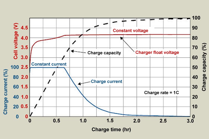
But, while you said the battery was Lithium, you really need to know the specific chemistry as some can be quite dangerous without specific charging parameters. If it's LiFePO4, it's pretty safe. Most battery charging sequences start off with constant current, then switch to constant voltage, and then either stop or go into a third state. If there's a part number on your charger you can might be able to find a datasheet for it and find out exactly. If your battery has a BMS, it may have over-voltage protection too as a second layer of safety.

The big concern for most chemistries is charging too fast which causes heat. With a maximum of 200W of solar that's probably not a concern here.
 
Before digging into the aluminum case after the battery pack... take a look at the charger. Does it just output constant voltage/current like a regular AC adapter (e.g., wall wart)? if so, all the "brains" might be inside with your battery and you just need the booster to duplicate what the charger is doing. Looking up that part number or testing the voltage it outputs over time as the battery charges can tell you a lot.
 
Wow! Great Photo!


This is a very valid concern and the answer is "it depends". Do you have any photos of the battery pack and/or circuitry? Also, how comfortable are you at taking voltage readings?

If you take the voltage reading of your fully charged battery, it'll probably be something around 51.2V for a 48V battery. For current to flow, there has to be a voltage difference. So, if the maximum your boost converter is set for is the battery's maximum voltage then you can never overcharge the battery.

But, while you said the battery was Lithium, you really need to know the specific chemistry as some can be quite dangerous without specific charging parameters. If it's LiFePO4, it's pretty safe. Most battery charging sequences start off with constant current, then switch to constant voltage, and then either stop or go into a third state. If there's a part number on your charger you can might be able to find a datasheet for it and find out exactly. If your battery has a BMS, it may have over-voltage protection too as a second layer of safety.

The big concern for most chemistries is charging too fast which causes heat. With a maximum of 200W of solar that's probably not a concern here.
i have tried taking the reading of the battery on full charge and it is shown as 50V at my multimeter.

So, would you say that the battery will never over charge if i set my dc-dc boost converter output voltage to 55v constant?

And yes, I am only using 100w x 2 mono panels in parallel because to avoid shadow effecting the voltage and amperage.

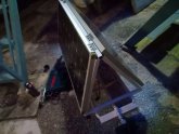
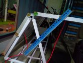
here's how my trailer with the solar panels look like (see attached photos)

the solar panel will not be flapped up for more exposure when moving and to reduce width of the trailer to prevent hazard to road users and my route will be hilly and have a lot of corners too.

but when I stop for drink/camp i will flap either one side of the panel or both directly to the sun to get max power to quickly charge the battery.IMG20191206191838.jpgIMG20191206214509.jpg

On top of the question, do you think charging and discharging the battery at the same time will damage the battery?

The bike is 350w brushless DC
Battery is 48v 11Ah
range is 40 km fully electric
 
...the battery on full charge ... [is] 50V... will [the battery] never over charge if i set my dc-dc boost converter output voltage to 55v constant?
Only if the "brains" are not in the "charger" (e.g., it's in the aluminum case with the battery). What I'm saying is that if you charge a battery without any sort of controller at 50V, the battery can never go over 50V and should be safe as long as the charging current is low enough. If you charge at 55V, then the battery would try to reach 55V (which would be bad for it if the max voltage is 50V).

That the max voltage is 50V at the battery terminals probably means it is NOT LiFePO4; so you'll need to be very careful with it.
 
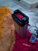
this is my battery pack photo (attached)

and this is probably the same spec of battery sold in alibaba. A rear battery.

So is it true it has integrated over charge controller?

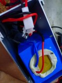
I have opened the casing just now but I cant see anything under the blue plastic as the battery already glue (photo attached)

So can i can connect directly from dc-dc boost controller to the battery charging input and it will automatically cut the charging process once full?

I can program my dc-dc booster to constant dc output to 50v at Amperage around 2-3A

because my solar panel will generate around 8A if both panel exposed but the booster will reduce the Amp once Voltage is increased to around 3-4A or lower IMG20191207081700.jpg

IMG20191207082331.jpg
 
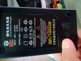
Does the charger have a specification label ?

Can you post a pic of it? Also, can you plug in the charger, and measure the voltage it puts out?

50V doesn’t translate into any battery chemistry... so, either your charger isn’t fully charging the cells, or your meter isn’t registering the pack voltage correctly.
 
This is the charger label .

And what comes into my suprise is, my 100w panel output only 0.45A even when the intensity of sun is high and positioned directly to the sun.

Do you think anything wrong with my panel?
I connect both 100w in series. it should come out at least 3-5A before boosted1575688410812779906622924124698.jpgIMG20191207100905.jpg
 
How are you connecting things to measure the amps output of the panels?

.45 is nothing... bad panels to be sure.
100watts at 48v would be over 2 amps.
 
You might have the two panels connected parallel, and tied to the battery, nothing is charging because the output is too low a voltage.
To push amps, there needs to be an imbalance voltage. The cells have to be above the battery voltage.
 
Ok, is your boost controller adjustable? Your ac charger is outputting 54.5v, so if your boost can be set to 54v, it should charge the bike cells.
 
Hi Azree,

Bad news. From the photo of the charger you can see it's meant for "Lithium Ion" batteries; these batteries can explode. Even if you do everything correctly, there's a possibility of a manufacturing flaw that can end up hurting you. I really can't recommend this as a first DIY project and if you decide to proceed highly recommend you take all possible precautions (for example safety glasses to protect your eyes). Please read up carefully on all the dangers around lithium ion batteries; there are lots of little things that can trip you up (e.g., if the voltage becomes to low the battery will not take a charge afterwards and could be considered dead forever).

I didn't see any evidence of a BMS or "brain" inside of the aluminum case in the photo, nor a part number on the charger. So, being cautious, I'd assume the charger had some sort of sensor and that it didn't output a steady 54.5v. You can test the voltage of the charger's output over the charge cycle to know for sure what it is doing.

How do you know when the battery is fully charged? Is there an indicator light somewhere? I'm wondering if the "brain" is in a 3rd location. There's something I can't make out under the wires/white-connector in the photo, possibly a fuse or low-voltage cutoff? Any part numbers on it or a better photo?

Regarding the solar panel, how are you measuring the amps? Most likely as @Supervstech said it's something unaccounted for in the measuring technique. I can see one panel being bad / damaged; but two makes the odds more in the circuit it's being test in.
 
Going back to your original idea of panels->boost converter->inverter->charger; you might try hooking them up one at a time and testing the output voltage of each stage to see how it goes. Worse case is it doesn't work; next worse is that it's just inefficient. If the boost converter's output is "regulated" to 24V it's just a question if it can handle the power load and if the inverter/charger can output the proper voltages at reduced current. If the voltage isn't regulated, you might have to play with the voltage setting during the charge cycle to keep it in the sweet spot. The good news about that is inverters are typically designed to handle some variance in input voltage.
 
If there are no "brains", it's probably thirteen lithium ion cells which would be charged at 4.2v per cell, that would make sense of the 54.5v; in which case it's a "dumb" constant output charger. Although this doesn't account for the full charge at 50v; possibly there's a high-voltage cut-off to prevent cell-damage or the full-charge indicator trips early. More here: https://batteryuniversity.com/learn/article/charging_lithium_ion_batteries

new.jpg
 
Hi Azree,

Bad news. From the photo of the charger you can see it's meant for "Lithium Ion" batteries; these batteries can explode. Even if you do everything correctly, there's a possibility of a manufacturing flaw that can end up hurting you. I really can't recommend this as a first DIY project and if you decide to proceed highly recommend you take all possible precautions (for example safety glasses to protect your eyes). Please read up carefully on all the dangers around lithium ion batteries; there are lots of little things that can trip you up (e.g., if the voltage becomes to low the battery will not take a charge afterwards and could be considered dead forever).

I didn't see any evidence of a BMS or "brain" inside of the aluminum case in the photo, nor a part number on the charger. So, being cautious, I'd assume the charger had some sort of sensor and that it didn't output a steady 54.5v. You can test the voltage of the charger's output over the charge cycle to know for sure what it is doing.

How do you know when the battery is fully charged? Is there an indicator light somewhere? I'm wondering if the "brain" is in a 3rd location. There's something I can't make out under the wires/white-connector in the photo, possibly a fuse or low-voltage cutoff? Any part numbers on it or a better photo?

Regarding the solar panel, how are you measuring the amps? Most likely as @Supervstech said it's something unaccounted for in the measuring technique. I can see one panel being bad / damaged; but two makes the odds more in the circuit it's being test in.
Hi Svetz
Sorry for gone missing for a while

Upon checking with the battery manufacturer, the battery indeed has BMS in the blue packet.
The charger is just giving constant Voltage and Amp to charge the battery (Converting AC to DC)

So, having said that the 'third party' here is the main brain isvery unlikely since the BMS will protect the battery from Overly Charged.
And the charger adaptor just have a small light indicator when there's current running (To show when it's charging or when the battery is already full), Which is here: Red and Green light.
I have opened the charger adaptor and it's only AC-DC converter and current flow IC with fan.

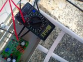
So, today I managed to go to an electronic shop nearby and bought 5A and 15A Analog DC Ammeter just to assist me better in understanding the current coming from the solar panels and the the current being output from the DC_DC Boost Converter.

So,hopefully if the weather is on my side tomorrow, I will try to connect all of those Ammeters and try to see the charging process for around 1Hour (If I get constant 4A++ output) as my battery is 80% full.

If after 1 hour the ammeter still indicates any current still going into the system, then I will stop the experiment and cut the circuit.

Maybe if the whole thing is a failure, I will then source for an adjustable 30A MPPT and let the MPPT does the charging rather relying on the DC-DC Booster/Converter

Does this sounds alright to you?
Anyway, appreciate the time invested to my thread for both of you.

Maybe if you're fine, we can communicate directly using Whatsapp/Facebook.
I'm in Malaysia now by the way and the whole plan is to ride this eBike from Kuala Lumpur to Bangkok (1400 KM) overland haha
 
How are you connecting things to measure the amps output of the panels?

.45 is nothing... bad panels to be sure.
100watts at 48v would be over 2 amps.
Hi, I just discovered that my multi-meter fuse blew off. Hahah
Upon short circuiting the panel using another multimeter, I get around 10A-11A when I faced both panel towards the sun.

Just get myself a new Ammeter today and will try again tomorrow (it's midnight now in Malaysia)
 
It sounds like you're onto it! Post questions/photos, best to be safe when you can and there are a lot of knowledgeable folks here that can probably help with anything you come across.

...Sorry for gone missing for a while ...
That sounds more like me ?, so much to do and so little time! I don't use facebook or other systems.
 
No problem, I'm cool with the efforts and all replies in here. Much appreciated. Keep in touch and I will keep on sharing my finding from my project :)
 
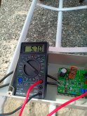
here's the amperage around 11am while it's slightly cloudy. Highest i got was 9.83AIMG20191208123120.jpgIMG20191208123642.jpg
 

Attachments

  • IMG20191208123650.jpg
    IMG20191208123650.jpg
    269.4 KB · Views: 3
It sounds like you're onto it! Post questions/photos, best to be safe when you can and there are a lot of knowledgeable folks here that can probably help with anything you come across.


That sounds more like me ?, so much to do and so little time! I don't use facebook or other systems.
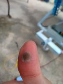
I just got electrocuted with 80v 1A
damn! that's painful.

burned my fingerIMG20191210114214.jpgIMG20191210115522.jpgIMG20191210114156.jpgIMG-20191210-WA0008.jpegi tried to clip this alligator clip on comverter output turned out it sparked as my thumb is slightly wet. lucky me i'm wearing rubber slipper and manage to pull my hand, fuck still burning now haha
 
I guess, the best bet is to add another 100W panel and connect all in series and ditch this 100W X 2 parallel arangement.
Means making it 18V X 3 without the use of converter.

So hopefully when I stop and setup the panel I can get 54V 4A or 5A when all are in series.
1A is too slow to charge my 48V 11Ah battery, I want to commit to minimum 120KM per day whichfull charge will gives me 40KM range fully electric.

ActivityDistance / TimeStop
Checkout fully charged and start riding 40KM (7am-9am)1. Charging for 2 hours 54V 4A (9am-11am)
Second riding session40KM (11am-1pm)2. Charging for 2 hours 54V 4A (1pm-3pm)
Third riding session40KM (3pm-5pm)3. Checkin/lodging (5PM) and charge using AC
 
I just got electrocuted with 80v 1A...damn! that's painful.
See http://www.diysolarforum.com/threads/frequently-asked-questions.70/post-7288.

Had you been using two hands (or what usually happens is one hand is unthinkingly resting on a ground), you'd probably be dead.
Capture.PNG
Let Azree's learning experience be a reminder to everyone you can never be to safe! Use disconnects and de-energize circuits before working on them. This can be a fun and rewarding hobby, but electricity can also kill you and as you can see in the chart to the right, it doesn't take much hand-to-hand current.
 

diy solar

diy solar
Back
Top