diy solar

diy solar

Grounding... - Need Help Simplifying

rs14smith

New Member
Joined
Apr 15, 2021
Messages
21
Hi all,

Let me try to explain my current setup without an image:

  1. I have a 100 Watt Renogy solar panel, that will be attached to a Renogy metal mounting bracket, that will be attached to the side of a wooden post.

  2. I have a cheap outdoor-rated Walmart plastic tote that is currently housing my 12V deep cycle battery, and charge controller.

  3. I have the solar panel connected to my charge controller, and my battery connected to the charge controller.

My question is, I am aware that grounding is necessary, but since I am dealing with a plastic tote, I am having difficulty figuring out how the electrical code applies.

What I do know, and correct me if I am wrong, I need to drive a 5/8" grounding rod into the ground 8' and attach a 6 AWG copper conductor to the grounding rod to my solar panel frame (using a grounding lug).

What I do not know is, for my electrical equipment inside the plastic tote, do I need to connect the DC- connection from the battery/solar panel to the grounding circuit? And if so, can I just use a basic bus bar to make those connections?

Thanks for any help, and I also know it is probably best to check local codes, but I typically have a hard time finding/understanding that information, so just looking for some basic advice/direction.
 
Where is this mounted? By that I mean is this a lamp on a fence post on a ranch? Or is this on or near your house where people might touch it?

What is the load? By that I mean where is the electricity consumed?

If it's an isolated system in a field and your load is DC powered by the battery, I'd say you do not need any ground. Think of it like a mobile system which has no ground, ie a big solar calculator or solar-powered wildlife camera. On the other hand, if this is mounted near a house yes you probably want to ground the metal frames of the panels and the metal chassis of whatever houses the load. Or, if you have an inverter you would want a real ground for the output of that AC 3-wire system. In this case, you typically want to tie the negative of the battery to the ground through a ground-fault interruptor.

Having said that; you can obviously run AC without a ground; that's how inverters like in gas generators work. They don't ask you to install a ground rod. My solar inverter has a jumper internally which allows you to tie the AC ground output to the neutral, or not do that, depending on whether you are providing a ground externally.
 
Last edited by a moderator:
Where is this mounted? By that I mean is this a lamp on a fence post on a ranch? Or is this on or near your house where people might touch it?
It is mounted on the wooden wall for my upper outside deck, so not quite attached to the house, but attached to the lower portion of my 2nd level outside deck.

If you are about 5.5' or taller, you could probably touch it, so I definitely think the panels/mounting system needs to be grounded.

What is the load? By that I mean where is the electricity consumed?

The system is only DC, no inverter. I use it to power a DC transfer pump for my garden and planning on adding a Wyze security camera to the system (using a 12v to USB adapter). My motor can draw 10Amps max, and the camera will draw a 4-5 Watts max.

On the other hand, if this is mounted near a house yes you probably want to ground the metal frames of the panels and the metal chassis of whatever houses the load.

So in my case, I do not have a metal enclosure to house my load. For now, I've put everything (battery, charge controller, and transfer pump) in a large plastic tote. My charge controller is mounted to a wooden bracket I made inside the tote. So the only metal components are the devices (charge controller heat sink, transfer pump body, and battery terminals) themselves.

I've never used a ground-fault interruption device in DC systems, but do I just need to mount a ground-fault interruption device in the plastic tote and wire up the battery negative and earth ground connection together using the ground-fault interruption? Also, do you have any links to any for small DIY systems just so I can verify I'm looking at the correct device?

Thanks
 
@FilterGuy has 4 resources on the topic you may wish to read, here is the first (I'll leave it to you to use the search and find the rest).

 
I've never used a ground-fault interruption device in DC systems, but do I just need to mount a ground-fault interruption device in the plastic tote and wire up the battery negative and earth ground connection together using the ground-fault interruption? Also, do you have any links to any for small DIY systems just so I can verify I'm looking at the correct device?
Like @Just John linked, those are some really nice diagrams from @FilterGuy, and you should read all 4 of those documents. The grounding of the frames (and pump body) is to release any static electricity, potentially avoiding a lightning strike, although it's totally inadequate if lightning actually did strike the panel. I assume your pump has a ground lug as well as DC terminals, although I admit I've never seen a DC pump so maybe it only has 2 connections. The pump body is in conductive water and would not be susceptible to lightning strikes or charge buildup.

For a small system you can probably forego the ground fault protection, although he does show it both ways in his diagrams. The ones with the protection breaker are just replicas of the same diagrams from manufacturers like MidNite Solar and OutBack Solar (two companies that sell those ground fault interrupting breakers).

What you give up when you do that; specifically if you just tie the battery negative to ground, is protection if one of the PV leads get shorted to the panel frame, for example from damage to the panel. This is an unlikely event, but if it happened, current would flow in the remaining lead and the ground; with the ground current passing through the sensor breaker back to battery negative. The sensing breaker would detect that current and shut off the PV (+) lead (as well as that ground-conducting path that should not have been conducting current). If you didn't have the breaker and this unlikely damage occurred, the panel frame could potentially have the PV's voltage, which I think is 12V in your case.

My personal opinions are perhaps a bit more cavalier than the official NEC-approved way to wire such a small system. I'm not an electrician, although neither is @FilterGuy. For a 100W, 12V panel and a purely DC load, here's what I would do:
- not worry about ground fault protection. Tie the battery negative directly to the earth ground.
- not go to the great lengths of embedding an 8 foot copper rod in the ground for a pond pump. But I would ground the panel frame somehow. I would look for an existing grounded circuit, a large piece of metal in the pond or ground, or else drive several feet of rebar into the wet ground near the pond. I think any of those would sufficient to dissipate static charge buildup on the panel frame.
 
Last edited by a moderator:
Like @Just John linked, those are some really nice diagrams from @FilterGuy, and you should read all 4 of those documents. The grounding of the frames (and pump body) is to release any static electricity, potentially avoiding a lightning strike, although it's totally inadequate if lightning actually did strike the panel. I assume your pump has a ground lug as well as DC terminals, although I admit I've never seen a DC pump so maybe it only has 2 connections. The pump body is in conductive water and would not be susceptible to lightning strikes or charge buildup.

For a small system you can probably forego the ground fault protection, although he does show it both ways in his diagrams. The ones with the protection breaker are just replicas of the same diagrams from manufacturers like MidNite Solar and OutBack Solar (two companies that sell those ground fault interrupting breakers).

What you give up when you do that; specifically if you just tie the battery negative to ground, is protection if one of the PV leads get shorted to the panel frame, for example from damage to the panel. This is an unlikely event, but if it happened, current would flow in the remaining lead and the ground; with the ground current passing through the sensor breaker back to battery negative. The sensing breaker would detect that current and shut off the PV (+) lead (as well as that ground-conducting path that should not have been conducting current). If you didn't have the breaker and this unlikely damage occurred, the panel frame could potentially have the PV's voltage, which I think is 12V in your case.

My personal opinions are perhaps a bit more cavalier than the official NEC-approved way to wire such a small system. I'm not an electrician, although neither is @FilterGuy. For a 100W, 12V panel and a purely DC load, here's what I would do:
- not worry about ground fault protection. Tie the battery negative directly to the earth ground.
- not go to the great lengths of embedding an 8 foot copper rod in the ground for a pond pump. But I would ground the panel frame somehow. I would look for an existing grounded circuit, a large piece of metal in the pond or ground, or else drive several feet of rebar into the wet ground near the pond. I think any of those would sufficient to dissipate static charge buildup on the panel frame.
Thanks for the reply. I read all 4 guides FilterGuy wrote and they were useful but did add more complexity to what I thought would be a simple system.

I'm trying to follow the NEC guidelines to a reasonable point, and I am fine with hooking up the GFP just to learn more about it and be compliant, but trying to find the cheapest one for my very small application. I do think it may be over kill for my application, but again, I'm trying to increase my knowledge and practice using it first hand.

I saw a GFP from Midnight solar, but it was roughly $54 from the source I found. Does anyone know of any others for a small system like mine (100W 12v)?
 
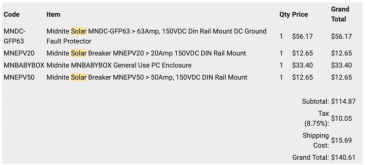
I do not know of a cheaper option. You also don't want to buy substandard components and have them not work or catch fire. For comparison I paid $140 for a MidNite box, two breakers, and the GFP double-breaker. Although $25 of that was tax and shipping. Again I wouldn't do a GFP with your system as 100W of solar at 12V is less dangerous than my system which is about 8x that size.

1618762310932.png
 
I would not be concerned in the least of grounding a 100 watt panel on a wood post or propped up in the dirt or wet lawn. Every metal object in the yard does not need a ground strap.
Same for the tote containing a battery or even an inverter. Nobody drives an 8' ground rod every time they fire up a portable generator.
 
  • Like
Reactions: reg
Every metal object in the yard does not need a ground strap.
I totally agree. However I would argue that every metal object permanently installed and connected to a car battery does deserve a ground!
 
I totally agree. However I would argue that every metal object permanently installed and connected to a car battery does deserve a ground!

Yes, my application would be permanently installed and connected to a battery. Also, I noticed most of the components you listed you purchased for your application are din rail components. For my DIY tote application, as I mentioned, most of my electrical components are screwed down to a wood bracket I made. Would you recommend if I wanted to use a proper solar breaker, and GFP to just buy a din rail and mount it to the wooden bracket, or are there some weatherproof enclosures (that include din rails) out there that could fit the necessary breakers for a reasonable price?

The primary issue with my setup is, all my hardware is placed outside, and I do not have a shed or easy way to route all the wiring back into a house.

I wish there was a guide/video somewhere that shows a "simple" professional setup using a proper outdoor enclosure that housed the solar disconnects/breakers, GFP, fues, etc. and maybe only the battery and solar controller (it screws down, no metal enclosure) I would leave in the plastic tote.
 
The enclosure I used is not weather proof. All "professional" breaker/combiner boxes installed outside are obviously weather proof. But, you don't even need breakers; you could just use fuses near the battery, inside your plastic tote. For example: an MRBF dual-fuse that mounts directly to the top of your battery terminal:


Then you don't need a breaker box at all. I was giving an example because you asked about ground fault protectors so I showed you what I bought. For your system I think some fuses (one for solar -> battery and one for battery -> load), and no ground fault protection, is appropriate.

This is what I'm thinking as well. Is it once I have a system that is over 50V that I need to probably revisit this subject about grounding and really try to follow it closely? I know you aren't licensed, but I'm sure you know 10x times more about this than I do, and I'm trying to keep this project DIY friendly and keep it reliable but affordable.

Thanks
 
The voltage is one thing, but it's also the current. Just a few milliamps across your heart can kill you. So I wouldn't say the problem is whether you're above or below 50V; although certainly higher voltage is more dangerous than lower voltage.

Like I said above, if you really want the lowest-effort / DIY grounding, just buy a stick of rebar and hammer it into the ground. That's not a big cost of money or effort for your project, in my opinion. I personally wouldn't go one step lower to "no ground" like some other forum members are suggesting, but you could do that too if you choose to.
 
Last edited by a moderator:
Hi all,

Let me try to explain my current setup without an image:

I have a cheap outdoor-rated Walmart plastic tote that is currently housing my 12V deep cycle battery, and charge controller.

.
IMO I would move the charge controller to it's own waterproof box.
I put my charge controllers in something like this https://www.amazon.com/Electrical-Boxes/b/ref=dp_bc_aui_C_4?ie=UTF8&node=495308
Drill the bottom and use gland seals for the wires.
What I found was a battery box that's not vented real well will corrode not only the battery terminals but any other exposed metal.
Tinned or silver coated copper wire is your friend as well as a tube of dielectric grease.
Good information. The more I think about the project, the more I am starting to maybe go a similar route you are mentioning just to somewhat maintain a professional look.

What type of enclosure would you use for the battery? I've seen a few but just curious from a person already into solar.
 
Back
Top