diy solar

diy solar

Is My Wiring & Grounding Theory Correct (Image Attached)

rs14smith

New Member
Joined
Apr 15, 2021
Messages
21
Hi all,

I've reviewed several grounding related documents here on this website, and yes, even the ones written by FilterGuy and the popular grounding video on YouTube. Still have some doubts, but hoping to clear some concerns up in this post.

I really need some help confirming if I have the necessary breakers included and wired correctly, and if I have the grounding circuit (GFP, grounding rod, etc.) wired correctly.

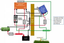
Note, my charge controller, breakers, battery will be in plastic enclosures which aren't drawn in the attached image.

I've took some time to sketch out a drawing of how I plan to connect everything and the parts being used.

My system specs (which are also in the attached image):

  • Solar Panel: 12v 100W
  • Battery: 12v 35Ah
  • Charge Controller: Pro-Star 15
  • GFP: MNDC-GFP63
  • Devices Powered By System: 12v 10A water transfer pump
 

Attachments

  • Screen Shot 2021-05-24 at 2.17.55 PM.jpg
    Screen Shot 2021-05-24 at 2.17.55 PM.jpg
    149 KB · Views: 68
Is your well pump going to run continuously? Unless I am mistaken, there is nothing protecting your battery from being completely discharged.
 
Ya w/o a switch for "on demand" to the pump motor that battery won't even make it through the day on a good day.
 
Is your well pump going to run continuously? Unless I am mistaken, there is nothing protecting your battery from being completely discharged.
No, the pump will not run continuously. This diagram is not focused on that end of the application, only the solar, breakers, gfp, grounding rod, etc.

I'm also not concerned about run time in this topic.

Ya w/o a switch for "on demand" to the pump motor that battery won't even make it through the day on a good day.

Hey Boondock, the pump has a switch, but as I mentioned to iamrich, this topic post isn't focused on that side of the system and I did not want to include all those details since my primary focus here is the grounding side, breakers, GFP device, and everything prior to the water transfer pump side.


So with that information, is the system prior to the water pump wired correctly and including the "necessary" components?
 
I see, you only want to provide half of the information. Ok then. Sounds like you have a plan.

I do not understand why I need to explain how I plan to use the water pump in my application. It’s irrelevant to mention that if my purpose of this thread is for something else.

Instead of attacking someone seeking help, why not try to help me understand why that information is so critical in order to help answer my question?


I would gladly provide it if necessary, but if this is the type of immaturity that takes place here in the beginners section of the forum, don’t bother, I’ll seek help elsewhere.
 
Last edited by a moderator:
Members PLEASE refrain from making snarky posts. This forum is for learning not antagonizing.
Ya I was just being snarky. Like rubbing balloons on your head to see if you'll get upset.

Whether you understand the use or not, it breaks down to 2 people asking you how you're going to run your system as you spec'd without any switch and you tell us you chose not to include that, it will be in a special upcoming edition. We weren't asking you how you will use the pump, we were asking about a crucial missing element in the circuit you made including "how I plan to connect everything and the parts being used."

Pump? check
Battery? check
Solar panels? check
Charge Controller? check
Breakers? check
Busbars? check
Ground rod? check
HEATSINK? check
Wood fence for upper deck? Ya, roger that too
Switch? Oh hell'nah!

You even threw in some wood and a ground lug termination, the heatsink, everything but the kitchen sink, but you refuse to throw in a switch and are perplexed about why people would care about that? Would you like for us to apologize for how we're wasting your time?
 
Never seen a ground wire connected through a breaker. I think it is better to go right on the bus.
I agree.....You can ground the negative bus bar though I don't think it is required.

If you what you could but the positive and negative solar wires through the breaker but not required.
 
I agree.....You can ground the negative bus bar though I don't think it is required.

If you what you could but the positive and negative solar wires through the breaker but not required.

Newbostonconst, unless I'm mis understanding something, a DC-Ground fault protector is now required on all PV systems. The GFP I am using in the attach image above is a MNDC-GFP63, and Midnite Solar provides a wiring diagram (see attached manual, first page) that instructs you to wire it that way (ground wire going to the bottom right side of the breaker, and battery negative going to the top right of the breaker).

Are you aware of this, or is there more to this I'm missing?

Thanks for taking the time to post.
 

Attachments

  • DC-GFP.pdf
    438.7 KB · Views: 13
If that’s accurate to your system it looks like the neg(-) to/through the breaker is 0.5A? That’s gonna trip for lightning or windstatic? Better than nothing but in my mind if lightning can find potential to dump its charge over mikes of open air will 3/8” in a breaker stop an oh-stink! moment?

my lawyer is off-grid 20+ years. Lightning hit a tree by the road two or three miles away. Along side her two-mile-long driveway (road) is buried a phone line. Phone line snuggled up to the atmospheric discharge snd fried the phone off the wall and killed her inverter and charge controller (cordless phone base was 120V and plugged in, and it backfed from that).

The lightning arrester on her panels did not get effected.

so I just wonder about that breaker

FWIW I run a Leviton 120VAC twist-to-set 30 minute timer on my water pump circuit (6A, 12VDC). I never worry about the pump running... the Leviton timer switch doesn’t seem to mind the DC amps but if it burns I’ve got it fused 8A.
You might try that?
 
Newbostonconst, unless I'm mis understanding something, a DC-Ground fault protector is now required on all PV systems. The GFP I am using in the attach image above is a MNDC-GFP63, and Midnite Solar provides a wiring diagram (see attached manual, first page) that instructs you to wire it that way (ground wire going to the bottom right side of the breaker, and battery negative going to the top right of the breaker).

Are you aware of this, or is there more to this I'm missing?

Thanks for taking the time to post.
Nope....not aware....thanks for sharing...

When I hear ground fault I think of a special breaker and not a 0.5 amp breaker between ground and negative.

So the idea for those that don't want to open the document(and his drawing) rs14smith shared. It has a breaker that will trip off the solar positive if the potential current going between the battery minus and ground gets larger then 0.5amps.

I have studies NEC a lot over the years and never seen this. I work in engineering in machine controls in plants, plus house wiring, plus solar, and have used double breakers to trip off battery/PowerSupply power plus and minus if just one of the legs flows too much...

Thanks, you learn something new everyday....that is a great life.
 
Newbostonconst, unless I'm mis understanding something, a DC-Ground fault protector is now required on all PV systems.
Are you describing something like this?

1621966433805.png

My system is not like this. It runs PV -> Combiner -> LV2424 all in one (SCC and Inverter) -> AC out to main Panel. My ground follows this path and doesn't bond with neutral until the main panel.
 
Are you describing something like this?
Not exactly, I'm basically describing or implementing something like what FilterGuy & Midnite Solar included in their GFP diagrams. (see link below for FilterGuy's post on Ground Fault Protection On Solar Panel Arrays):

According to the snippets I'm seeing about the NEC on this topic or in FilterGuy's PDF, it seems the primary reason you install the GFP is if you are installing the system in/on a building to help prevent fires, not shocks.
 
I have never seen this. I just read both articles. I don't think most DIY off grid systems are using this, I know mine isn't. Definitely something to think about though.

If I understand it correctly if the PV array starts bleeding power into the ground wire it will pop the ground breaker which is ganged to the positive breaker which would break flow of power form the array. I don't see why a PV array would bleed voltage to ground, I assume some kind of short or failure in one of the panels. I doubt I will implement this on my current setup, but like I said worth looking into. My setup is on a metal roof on a detached garage, so the risk to humanity is pretty limited.
 
Back
Top