diy solar

diy solar

Can someone check my 400w Setup?

kenkoh

Solar Enthusiast
Joined
Jan 10, 2020
Messages
527
Location
Las Vegas & Pennsylvania
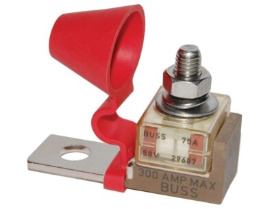
I'm new & know nothing much. Let me know any problems with this thanks. I'm not sure about where the 175a bolt on fuse go and what I found on Amazon says 175amp & '32V' is that the right one?

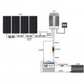
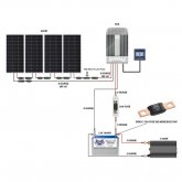
I'm using a 40a charge controller, 4x 100w panels, 1500w pure sine wave ca& a single Battleborn 100a lithium battery. I get 4 hours sun average & I need to power a single 15 Macbook Pro (87w) for 11 hours everyday thats it. As I understand it a single 1200w hr battleborn should do it (1200/87w = 13).

Will this fuse work for solar?
 

Attachments

  • CHECK-5.jpg
    CHECK-5.jpg
    50.6 KB · Views: 34
Last edited:
I'm new & know nothing much.
Sorry, this did make me laugh! :) Welcome to the club!

I'm not sure about where the 175a bolt on fuse go and what I found on Amazon says 175amp & '32V' is that the right one?
Yes, and no. I am making the assumption that this 175A fuse came with a kit of some sorts, so you'd prefer to use it rather than buying a new one. So the quick answer to your question is this fuse should go on either the battery or inverter's positive connection.

BUT, please consider:

Fuses are there to protect the cable from potential short circuits, and, to a lessor degree, the device they are connected to. Your inverter at 1,500W is rated to provide 125A (1,500W / 12V = 125A) so fusing below that would obviously blow in normal use. The cable you are using i.e. 02AWG is rated for 170A (according to here) so fusing above that puts your cable at risk. Most people settle on a rule of thumb of operating current +25%, so for your application this would be 156A (125A +25% = 156A) or to the nearest fuse, probably 150A. There is probably no significant danger using this 175A fuse but know that you are using it outside the specifications of your cable.

ALSO consider:

Having a fuse hanging off a battery or inverter is an accident waiting to happen. I personally would use a covered, fused holder like this or better still this (the one on the right is the one I actually use in my system)

2020-01-21_17-06-01.png 2020-01-21_17-06-33.png

Will this fuse work for solar?
Generally speaking, automotive style/spec fuses are fine for solar BUT if you do need to be careful with larger arrays - multiple panels in series can exceed the usual 32V voltage specification for automotive equipment. But to answer your question, with the above considerations, this will be fine. Personally, I trust 'Little Fuse' for everything circuit protection-wise.

Edit: Corrected typo.
 
Sorry, this did make me laugh! :) Welcome to the club!


Yes, and no. I am making the assumption that this 175A fuse came with a kit of some sorts, so you'd prefer to use it rather than buying a new one. So the quick answer to your question is this fuse should go on either the battery or inverter's positive connection.

BUT, please consider:

Fuses are there to protect the cable from potential short circuits, and, to a lessor degree, the device they are connected to. Your inverter at 1,500W is rated to provide 125A (1,500W / 12V = 125A) so fusing below that would obviously blow in normal use. The cable you are using i.e. 02AWG is rated for 170A (according to here) so fusing above that puts your cable at risk. Most people settle on a rule of thumb of operating current +25%, so for your application this would be 156A (125A +25% = 156A) or to the nearest fuse, probably 150A. There is probably no significant danger using this 175A fuse but know that you are using it outside the specifications of your cable.

ALSO consider:

Having a fuse hanging off a battery or inverter is an accident waiting to happen. I personally would use a covered, fused holder like this or better still this (the one on the right is the one I actually use in my system)

View attachment 5568 View attachment 5569


Generally speaking, automotive style/spec fuses are fine for solar BUT if you do need to be careful with larger arrays - multiple panels in series can exceed the usual 32V voltage specification for automotive equipment. But to answer your question, with the above considerations, this will be fine. Personally, I trust 'Little Fuse' for everything circuit protection-wise.

Edit: Corrected typo.
What about 8 or 10 guage from solar panels to charge controller? & the 10a in-line fuse? Can you check my updated diagram based on what you said? Thank you very much!
 

Attachments

  • CHECK-7.jpg
    CHECK-7.jpg
    46.6 KB · Views: 14
I just realize in Will's video he's connected the inverter to the charge controller what gives? Which is better?
 

Attachments

  • Screen Shot 2020-01-21 at 6.17.48 PM.png
    Screen Shot 2020-01-21 at 6.17.48 PM.png
    439.4 KB · Views: 13
Just a quick very design review:
  1. Your 400W array panels are connected in series, thus generating around 88Voc. Does you MPPT support this?
  2. Imp for a 100W panel will be about 6A (at Vmp or about 72V) so minimum cable size will be 18AWG (according to here) but you also want to minimise the voltage drop along the cable run to no more than 3% of the supplied voltage i.e. <2.2V. So how long is your PV cable run? Let's say 10m there and back. At 0.021Ω per meter that's 1.26V (V = IR, I=6A, R=0.021Ωx10m, V=1.26V). Therefore, 18AWG is a suitable cable for your application. Over-specifying your cable just adds unnecessary weight and cost to your project.
  3. I personally would not fuse the PV line (other opinions are available!) because the low current, even if shorted, would not cause any damage to the cable or panels. This advice would shift for larger arrays due to 'back feeding' of parallel runs. But if you do feel the need, a 10A fuse will be fine if you decide on 8 or 10AWG cable. MC4 connectors are rated up to about 20A.
  4. I would however include a PV and a battery isolation switch to allow you to work on the system un-powered.
  5. 8AWG cable from your MPPT is a little over specified, you could get away with 10AWG for a short run, but will be fine as is, and being fused at 50A seems reasonable (i.e. operating current +25% and less than cable rating)
  6. 2AWG is a good fit for your inverter.
  7. You might want to consider adding a -ive bus bar rather than fixing everything to your battery.
Voc = PV Voltage Open Circuit
Vmp = PV Voltage Maximum Power
Isc = PV Current Short Circuit
Imp = PV Current Maximum Power
 
1. Recommended by someone else on this forum: EPsolar TracerBN 40A 150V MPPT Solar Charge Controller
2. Could be 25 feet, I was just following Will's book.
3. I won't fuse the PV line now
4. OK I need to research that PV & Battery isolation
5. 10AWG it is
7. OK

THANKS!
 
I just realize in Will's video he's connected the inverter to the charge controller what gives?
I'm guessing it will just be a convenient method of connecting to the battery.
Which is better?
Personally I would want to fuse and be able to isolate the battery before it connected to anything, additionally I would always use bus bars to to inter-connect devices rather than connecting multiple things to one device. Technically does it matter? Probably not.
 
You are most welcome. Good luck with your new PV system! :)

One final point: be sure to use proper PV cable for your PV cable run. PV cable has UV resistance and tinned-copper conductors designed for outdoor solar use.
 
@tictag: nice detailed responses! Very clear and lots of good information and guidance in there.

2AWG is a good fit for your inverter.
@kenkoh: if you can afford it, I recommend using a larger gauge wire to the inverter (like 2/0 AWG - that's 00, it's bigger than 2 AWG). Even if the distance between the battery and inverter is short, you can't go wrong over-sizing those wires. In the future, if you run more than just the laptop and you get close to that max 125ish amps that tictag wrote about, you won't be heating up the bigger wires as much as the 2 AWG. Also, the 175A fuse you first wrote about would not be exceeding the capability of the 2/0 wires. I use this site as a reference for determining wire sizes.

Speaking of the fuse, you want to have that as close to the battery bank as possible. In addition to tictag's recommendations, you could consider installing this type of fuse and holder. It bolts directly to the battery terminal:

 
That fuse is cool. Thanks.

Which is better for my setup:
- 150amp fuse with 2 guage wire to inverter or 175amp fuse with guage wire?
 
Last edited:
New to solar but I have to ask....What determines fuse amp size that bolts on directly to +battery post?
 
New to solar but I have to ask....What determines fuse amp size that bolts on directly to +battery post?

If you are talking about the fuse between the inverter and the battery bank you would normally look in the inverter manual and it will tell you ... if not then industry standards is you take the Continuous Watts / Battery Voltage and multiply it by 125% or 1.25 ... so if you have an 12V 1000W inverter and it draws 85 continuous amps, you would go 85 X 1.25 which gives you 106 Amps, so typically the next size up from 106 is 150A fuse.... so I would use a 150A
 
If you are talking about the fuse between the inverter and the battery bank you would normally look in the inverter manual and it will tell you ... if not then industry standards is you take the Continuous Watts / Battery Voltage and multiply it by 125% or 1.25 ... so if you have an 12V 1000W inverter and it draws 85 continuous amps, you would go 85 X 1.25 which gives you 106 Amps, so typically the next size up from 106 is 150A fuse.... so I would use a 150A
Right on....exactly what I was talking about. Thanks
 
New to solar but I have to ask....What determines fuse amp size that bolts on directly to +battery post?
Whilst I do agree with @ghostwriter66, imho, fuses are there to protect the cable just as much, if not more, than the device connected to the cable; your inverter will have its own protection, as will your battery. I would recommend taking the lower value of the expected current (as @ghostwriter66 says) and the maximum rating of your cable. For example, if you fuse at 150A to protect your inverter but the cable connecting to it is only rated for 100A, the cable, and inverter, will still go up in flames! ;-) I'm kidding, it'll probably just get very hot, but you catch my meaning? Imho, it's best to think of the fuse protecting the cable e.g. from short circuit, than being required to protect the device.

Edit: Corrected grammar.
 
Last edited:
Please see the thread below for some additional fuse selection reference material.

 
Thank you again tictag. Other kind folks like you provided me with these charts I am using. I've decided to just go thicker and I don't need long cables anyway.


Please see the thread below for some additional fuse selection reference material.

You both rock! Even after reading Will's book many times, thanks to your confirmations I have a better understanding of putting my system together.
 
Hope this won't hijack OP's thread but I wanted to piggy back on this subject with a question of my own. Why are most Diy solar systems, at least the ones I've seen, use fuses instead of circuit breakers? I'm in the process of designing my system and leaning towards circuit breakers because it's a lot easier to flip a switch to disconnect a component for servicing and maintenance. If circuit breakers, like between the battery and charge controller/inverter, are acceptable, I would welcome any advice on which ones are best and which ones to say away from and why. Thank you.
 
Back
Top