Hey there!
A little confused with everything I'm looking at, and my setup isn't exactly what I would consider standard, so I would appreciate any resources or advice here.
Looking for feedback on how we may eventually go with a hybrid system with a battery. I am also considering using an EV (such as the Ford Lightning or another EV that allows using as a backup) to backup the house in the event of outages. Either way, it would be great to know how we might eventually get there.
I am getting solar in two weeks with a grid tied system with Enphase microinverters. I know we will not get power when the grid is off in this setup.
I attached a digram of the wiring from the home. Besides the 100A fuse potentially not being enough for the house in the future (especially if charging an EV), wouldn't any sort of inverter need to go between the electrical panels in the house and the grid? I'm not super familiar with how automatic shutoff and transfer switches work, or how you would isolate from the grid.
Image 1 is the current setup of the house.

Both of the electrical panels (house and garage) are connected to the two terminals coming off of the pullout fuse like shown in the diagram there. I imagine that would complicate things when trying to get the load to the house if we were to install a hybrid inverter at some point.
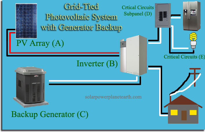
Image 2 is the anticipated setup with solar.

Image 3 is what I imagine we would need to do in the event of getting a hybrid/battery system?

Any feedback or advice would be appreciated! Also I'm not installing all of this myself, this is more just for my own understanding.
A little confused with everything I'm looking at, and my setup isn't exactly what I would consider standard, so I would appreciate any resources or advice here.
Looking for feedback on how we may eventually go with a hybrid system with a battery. I am also considering using an EV (such as the Ford Lightning or another EV that allows using as a backup) to backup the house in the event of outages. Either way, it would be great to know how we might eventually get there.
I am getting solar in two weeks with a grid tied system with Enphase microinverters. I know we will not get power when the grid is off in this setup.
I attached a digram of the wiring from the home. Besides the 100A fuse potentially not being enough for the house in the future (especially if charging an EV), wouldn't any sort of inverter need to go between the electrical panels in the house and the grid? I'm not super familiar with how automatic shutoff and transfer switches work, or how you would isolate from the grid.
Image 1 is the current setup of the house.
Both of the electrical panels (house and garage) are connected to the two terminals coming off of the pullout fuse like shown in the diagram there. I imagine that would complicate things when trying to get the load to the house if we were to install a hybrid inverter at some point.
Image 2 is the anticipated setup with solar.
Image 3 is what I imagine we would need to do in the event of getting a hybrid/battery system?
Any feedback or advice would be appreciated! Also I'm not installing all of this myself, this is more just for my own understanding.