waywaynorcal
New Member
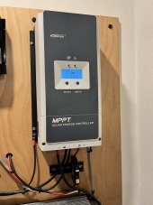
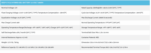
First and foremost.. I am not the brightest bulb in the string but through sheer tenacity I usually get things figured out. That being said I am having a difficult time with my solar setup. The setup is a 12v system with two Renogy 200 hybrid batteries linked together. My charge controller is an EPEVER 100 amp.
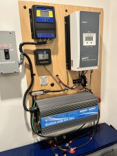
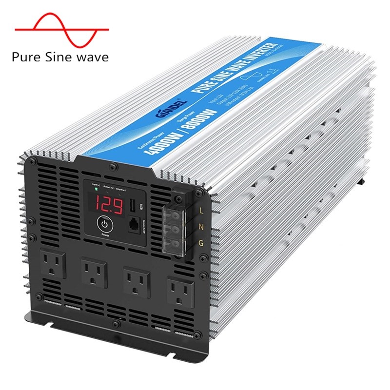
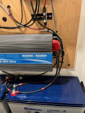
My inverter is a Giandel 4000w 8000w peak pure sine inverter 12v
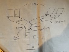
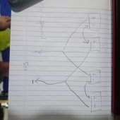
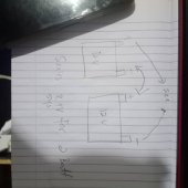
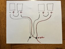
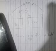
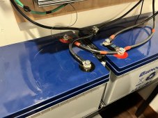
I have four 335 watt panels for a total of 1340 watts. The system is wired in a series like the photo below. And the batteries are connected pos to pos and neg to neg as shown in the photo below.
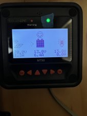
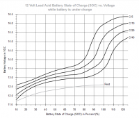
My issue is my two Renogy batteries dont seem to be holding a full charge. I have done as much as I can to try and figure out what is going on. I am not sure how to test to see if they are holding a charge and if they are is the charge what it should be relative to the panels and wiring I have. Basically I am lost with this system at the moment and it has become frustrating. The system also lets out a beep now and again. It seems to beep when it reaches full charge and when it is below the charge. It seems with the batteries fully charged it should be running more than a small fish tank and one LED light. The batteries are under a year old and I was very careful following the instructions when I set this up. Most all of this stuff is less than 2 years old.
from my calculations I have roughly 2,560 watt hours
below are a few photos from this afternoon.
OH The ATS is temporally disconnected until I figure this out. The inverter is off as well.
Any help would be greatly appreciated.
My inverter is a Giandel 4000w 8000w peak pure sine inverter 12v
I have four 335 watt panels for a total of 1340 watts. The system is wired in a series like the photo below. And the batteries are connected pos to pos and neg to neg as shown in the photo below.
My issue is my two Renogy batteries dont seem to be holding a full charge. I have done as much as I can to try and figure out what is going on. I am not sure how to test to see if they are holding a charge and if they are is the charge what it should be relative to the panels and wiring I have. Basically I am lost with this system at the moment and it has become frustrating. The system also lets out a beep now and again. It seems to beep when it reaches full charge and when it is below the charge. It seems with the batteries fully charged it should be running more than a small fish tank and one LED light. The batteries are under a year old and I was very careful following the instructions when I set this up. Most all of this stuff is less than 2 years old.
from my calculations I have roughly 2,560 watt hours
below are a few photos from this afternoon.
OH The ATS is temporally disconnected until I figure this out. The inverter is off as well.
Any help would be greatly appreciated.