diy solar

diy solar

Class T fuse Size for two LV6548 Controllers - with 4 48v LiFePO4 batteries

I am setting up the same 2 lv6548 system with the transfer switch also,

I have a question on the ac in wiring/grnding

my inverters etc are in a separate building about 100 ft from the main panel

This outbuilding is serviced by a triplex 3 wire , into a 125 panel with a grounding rod

my plan for ac in was to use a 60 amp breaker from the subpanel in the outbuilding to the inverters

can I run a 4 wire setup with ecg from this sub panel to the inverters ?

or, if not

can I run a separate ecg from the main panel 100 ft away to the inverters and use the other 3 wires from the subpanel to inverters ?

or... what would you suggest ?

thanks
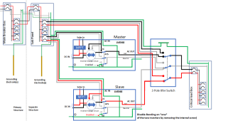
Being in a separate structure with a sub-panel does not really change the diagram much
1647703952573.png
Notice that the sub-panel does *not* have an NG bond.

As an aside: The grounding electrode(s) at the separate structure is proper to meet the NEC, but I am not sure why it is required.... and I do know some potential problems with the extra grounding electrodes. The best explanation I can come up with is that if there is a nearby lightning strike that causes a potential difference across the earth's surface, they don't want to have that potential difference show up between the metal of the structure and the EGC system. This could potentially give someone a really bad shock if they were touching both when the strike happens. However, the trade-off is that there will be a huge spike in the EGC system that could damage equipment.
 
Being in a separate structure with a sub-panel does not really change the diagram much
View attachment 87894
Notice that the sub-panel does *not* have an NG bond.

As an aside: The grounding electrode(s) at the separate structure is proper to meet the NEC, but I am not sure why it is required.... and I do know some potential problems with the extra grounding electrodes. The best explanation I can come up with is that if there is a nearby lightning strike that causes a potential difference across the earth's surface, they don't want to have that potential difference show up between the metal of the structure and the EGC system. This could potentially give someone a really bad shock if they were touching both when the strike happens. However, the trade-off is that there will be a huge spike in the EGC system that could damage equipment.

Thanks Filterguy
if I read your diagram right,
you are saying to run the ecg from main to sub panel, making that a 4 wire system
rather than run the ecg from main to inverters

I can do that, its about 50 ft more wire, but then at least the outbuilding will be wired to current code,I think 3 wires are no longer allowed
OOPS, I misread your original description and did not realize there was no EGC running from the main to the sub-panel.

You are correct that the current code requires the EGC from the main to the sub-panel and that is the proper way to set it up.

If you choose not to run the EGC from the main to the sub-panel, then the situation changes and there must be an N-G bond in the sub-panel in order to re-establish the low impedance fault current path.

1647711233088.png
 
@wayne530 and @FilterGuy just to make sure we are all on the same page when I refer to egc I mean this.
"5.DC Side Grounding Connector marked – Hole Dia 6.5mm for wire sizes up to 25mm2 (AWG #4). Set Screw M-8. This is internally connected to the metal chassis of the unit." -- 2.1 MAIN UNIT: LAYOUT-FRONT (FIG 2.1) in https://samlexamerica.com/wp-content/uploads/2020/01/11025-EVO-2212-3012-2224-4024-0322_Lrez.pdf
Hmmmm.... I guess we are not all on the same page.

In NEC terminology, Equipment Grounding Conductors are the Green or bare wires that run with the Hot & Neutral wires and bond all the non-conducting metal together.

In the diagrams I provided above, I indicate the case grounding screw on the inverters with the 1647713187258.png symbol. For the set-up I am describing, the case grounding screw would not be used. (The case is connected to the EGC system by the AC-In ground connection. Any additional connection to the EGC system would create ground loops)

The link you provided is for a Samlex inverter. With only a brief review of the Samlex manual, I do not see anything I would change in my diagrams.

A few notes on the Samlex.
1) I applaud the level of detail the manual goes into for grounding and bonding. It is a refreshing change from the complete lack of info provided by MPP and Growatt.
2) The method for disabling the bonding relay is to simply disconnect a 'quick connect' connector that is in the AC connections compartment.
3) The manual refers to the Neutral-Ground bonding as bonding the neutral to the case ground. While accurate, that is a strange way to refer to it.
4) The manual talks about using the Case Grounding Screw to bond to the chassis of a boat or an RV. This is fine, but that should be the only place that the AC EGC system is tied to the vehicle chassis.
 
I think I've confused everyone :oops:
Haha no worries. I personally started this conversation confused so I don't think I am any more confused :p I genuinely appreciate the discussion/help. We're all learning here! :)

If I understand @FilterGuy's diagram (and that's a big IF), I don't think anything from the inverter or premises is connected to the negative bus bars of the battery bank? The LV6548 does not have an equivalent EGC connector, at least not one that is externally exposed/labeled:

1647715371980.png
 
Sadly, the screw to disable the bonding relay is not documented in the manual. We only know about it via communications with MPP and the distributers. Unfortunately, I don't have access to a picture to show where the screw is.

[RANT MODE ON]
It is criminal how MPP and Growatt fail to document how grounding and bonding are handled in their equipment. This is a critical aspect for safely using their equipment but they completely ignore it!!!.
[RANT MODE OFF]
What's equally surprising is that MPP and the distributors sell a 2-inverter bundle. I've asked my distributor whether MPP has disabled the automatic N/G bond in one of the 2 inverters. I suspect no, but hopefully will be pleasantly surprised that they do. My understanding is that opening the inverter to remove this screw will void the warranty of the unit.
 
If I understand @FilterGuy's diagram (and that's a big IF), I don't think anything from the inverter or premises is connected to the negative bus bars of the battery bank?
Welllllll.... not quite. My diagrams do not attempt to show the DC side of things.

A 48V system can operate at a high enough voltage that the NEC requires one leg of the DC to be a grounded circuit. (The NEC does not specify whether the negative or positive must be the grounded, but for this community, we tend to always make the negative the grounded leg).

So.... someplace in the system, the DC circuit needs to be bonded to the EGC system. However, it should only be grounded at one spot.

As an aside: Most of the All-in-one units say not to ground the PV circuit. I understand this is for systems that have built-in PV ground fault detection... I am not sure this meets code for systems that don't have built-in PV ground fault detection.
 
Welllllll.... not quite. My diagrams do not attempt to show the DC side of things.

A 48V system can operate at a high enough voltage that the NEC requires one leg of the DC to be a grounded circuit. (The NEC does not specify whether the negative or positive must be the grounded circuit, but for this community, we tend to always make the negative the grounded circuit).

So.... someplace in the system, the DC circuit needs to be bonded to the EGC system. However, it should only be grounded at one spot.

As an aside: Most of the All-in-one units say not to ground the PV circuit. I understand this is for systems that have built-in PV ground fault detection... I am not sure this meets code for systems that don't have built-in PV ground fault detection.
Ah, got it! Would this be as simple as connecting the chassis of one of the inverters to the negative bus bar? As I mentioned, the MPP does not have an externally exposed EGC for this purpose. If this is correct, would it matter which chassis? Should it be the one that has the N/G bonded?
 
Ah, got it! Would this be as simple as connecting the chassis of one of the inverters to the negative bus bar? As I mentioned, the MPP does not have an externally exposed EGC for this purpose. If this is correct, would it matter which chassis? Should it be the one that has the N/G bonded?
If by EGC you mean dc ground lug...
If it doesn't have one I would check for continuity between the dc negative terminal and the ac ground.
If there is continuity that should be sufficient to keep the dc domain referenced to the planet.
 
"Ground" is only mentioned on 3 pages of the LV6548 manual and it doesn't mention anything about the battery bank and the part about PV is mentioned twice in the manual:
1647717337290.png
 
If by EGC you mean dc ground lug...
If it doesn't have one I would check for continuity between the dc negative terminal and the ac ground.
If there is continuity that should be sufficient to keep the dc domain referenced to the planet.
Sorry, yes, a DC ground lug. Even if there is continuity, I'm not sure the terminals are large enough to accept two conductors. I will investigate and report back. I'm sure others with LV6548 have figured out something. I'll do some searching on the forum as well.
 
Sorry, yes, a DC ground lug. Even if there is continuity, I'm not sure the terminals are large enough to accept two conductors. I will investigate and report back. I'm sure others with LV6548 have figured out something. I'll do some searching on the forum as well.
It doesn't need a second conductor.
The inverter ac ground wire is attached to the service entrance panel and the inverter dc negative wire is connected to the dc domain's negative busbar.
The allows the dc_domain to be referenced to the planet.
I use the word planet because earth and ground carry far to much baggage.
Ahh right, thank makes complete sense. I will test for continuity between these two terminals.
 
Ah, got it! Would this be as simple as connecting the chassis of one of the inverters to the negative bus bar? As I mentioned, the MPP does not have an externally exposed EGC for this purpose. If this is correct, would it matter which chassis? Should it be the one that has the N/G bonded?

1st: A lot of people do not ground their 48V DC. (I do not recall @Will Prowse grounding the 48V DC in any of his videos.)

It does not really matter where the DC is connected to the EGC. Something like this would work:

1647718393860.png

BTW: The NEC requires all grounded conductors to be color-coded white. Consequently, to strictly meet the code, the negative would need to be white. The good news is that it is acceptable to put white tape bands on a black wire to indicate it is a grounded conductor.
 
If it doesn't have one I would check for continuity between the dc negative terminal and the ac ground.
I would be very surprised if the DC negative is connected to the EGC/Chassie/ground inside the inverter.
 
I use the word planet because earth and ground carry far to much baggage.
You got that right!!!!

In NEC Nomenclature 'Grounded' and 'Grounding' are two totally different things.
A grounded conductor is a current-carrying conductor that is bonded to the EGC system.
A grounding conductor is the green/bare EGC wire and does not carry current in a normal operation.

When reading the NEC if you don't pay attention to 'grounded' and 'grounding' you will get totally confused. (I speak from recent experience)
 
The distributor confirmed that when two LV6548 are run in parallel inverter mode, both will have N/G bonding. They followed up by saying:
Both will have. This is not a problem
They also mentioned that the “warranty will not be affected” when removing the binding screw, so it seems the correct action here is to remove it from all units except one.

Given the N/G bond in the units is controlled by the device firmware, it seems like it’d be better for MPP to release a firmware update that either handles this automatically and/or provide user settings for more granular control of N/G bonding in the device.
 
Back
Top