diy solar

diy solar

Wiring advice would be so appreciated!

Gabrielle

New Member
Joined
Apr 11, 2022
Messages
76
I completed a setup and posted to this forum, where I received advice to rewire. So, working on the new set-up, trying to get it done today because I need to move into my RV asap! I'm still having trouble with the wiring.. I already posted this in the thread I started before, not trying to be spammy but posting a fresh thread thinking that might get more visibility?

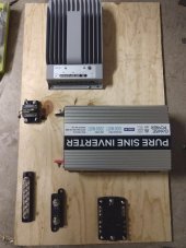
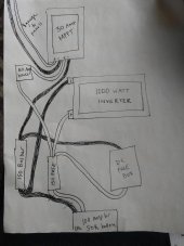
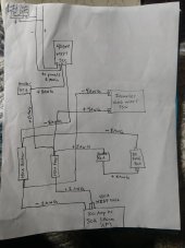
I attached pictures of the new set up, one my hand drawn interpretation of a schematic...

I have 8 gauge running to the panels and 2 gauge wire running from the battery to the busbar and 150 amp mega fuse.

I'm thinking I should do 2 gauge from the inverter to the busbar and fuse, 8 gauge for all the rest of the connections. My logic is coming from what I understand of Wills book, videos, reading on forums, but it's possible that I'm way off here.

Thoughts??

Thanks in advance for sharing your knowledge, I only want to (re)do this once so trying to get it right!
 

Attachments

  • 0-2.jpeg
    0-2.jpeg
    110.1 KB · Views: 31
  • 0-3.jpeg
    0-3.jpeg
    80.1 KB · Views: 31
A mega fuse really has no place on a lithium ion installation.

#2 cable will handle the continous output of the inverter, but not the surge potential.
How many amps are you allowing on the dc loads cable?
 
A mega fuse really has no place on a lithium ion installation.

#2 cable will handle the continous output of the inverter, but not the surge potential.
How many amps are you allowing on the dc loads cable?
Can you explain a little about the mega fuse?

The manual for the 1000 watt recommends #4 so I thought I'd be safe with #2 to the battery. And maybe #4 from the inverter to the fuse and busbar.

My dc appliances add up to 7 amps right now.. so maybe those cables should be way smaller?
 
A number of comments.

Any protection needs to be at the high power source end of cables, in this case the battery.

The fuse box will not be rated for more than 100 amp, perhaps less. Thus a fuse or breaker should be at the battery end of its feed cable, suggested fuse for the feed to fusebox, 30 amps.

The maximum continious discharge of the SOK battery BMS is 100 amps.

Due to the possible very high fault currents should the battery BMS fail, a fuse capable of withstanding these currents is advised at the battery.
Although a class T fuse with a 20k amps rating is often advised, most small battery 12v systems should be protected with a MRMF fuse. A MEGA fuse is only good for 2000 amps.

The inverter case is designed to be mounted vertically.

Mike
 
Hi Mike,thanks for your comments.

I'm a little confused on all counts. For the inverter are you sure? manual seems to recommend that orientation. My space worked well for vertical but I changed it after reading through it..

I have a mega fuse on the battery end now. mega fuse not of 2000 amps, but 150 Amps. This design is what I see Will doing in so many videos. never heard of a class T fuse and think I'll need to read up about fault currents.. so you're saying my fuse at the battery needs to be able to withstand 2000 currents??

As for the protection to the fuse box- i was thinking the fuse is protecting the wire. And since I have minimal Dc appliances that will pull 10-20 amps at most, I thought the fuse box can share the 150 amp fuse with the inverter.
 
A number of comments.

Any protection needs to be at the high power source end of cables, in this case the battery.

The fuse box will not be rated for more than 100 amp, perhaps less. Thus a fuse or breaker should be at the battery end of its feed cable, suggested fuse for the feed to fusebox, 30 amps.

The maximum continious discharge of the SOK battery BMS is 100 amps.

Due to the possible very high fault currents should the battery BMS fail, a fuse capable of withstanding these currents is advised at the battery.
Although a class T fuse with a 20k amps rating is often advised, most small battery 12v systems should be protected with a MRMF fuse. A MEGA fuse is only good for 2000 amps.

The inverter case is designed to be mounted vertically.

Mike
Hi Mike,thanks for your comments.


I'm a little confused on all counts. For the inverter are you sure? manual seems to recommend that orientation. My space worked well for vertical but I changed it after reading through it..


I have a mega fuse on the battery end now. mega fuse not of 2000 amps, but 150 Amps. This design is what I see Will doing in so many videos. never heard of a class T fuse and think I'll need to read up about fault currents.. so you're saying my fuse at the battery needs to be able to withstand 2000 currents??


As for the protection to the fuse box- i was thinking the fuse is protecting the wire. And since I have minimal Dc appliances that will pull 10-20 amps at most, I thought the fuse box can share the 150 amp fuse with the inverter.
 
About the 150 A MEGA fuse.
Suppose there is some fault in the circuit that allows full battery energy to flow through the fuse, ( let's assume the battery BMS has failed). The fuse metal link will vaporise but due to the high current the lithium cells can deliver, the plasma and physical dimensions of the fuse may still allow current to flow, ( think arc welder). MEGA fuse current withstand is 2000 amps.
Alternative fuse types withstand higher currents, classT at 20,000 amps and MRBF at 10,000 amps.( At 12 volts)

A 12 volt 100 Ah SOK battery is unlikely to deliver over 10,000 amps in the worst case, but may exceed the 2000 amps of a MEGA fuse.

An advantage of the MRBF is that the fuse and holder from Blue sea can be bolted directly on the battery posiitive.

Re the inverter. I guess it's fan assisted cooling so perhaps vertical mounting is less important.

The layout you are using as a basis for your system was a for demonstration.

A physical install in a van needs more care with over current protection, cable selection, and mechanical security of cables and components. There is the need to integrate with other systems, furnature layout and cooling ventilation of electronics.

Re the fuse share. A fault within thefuse box could allow the 150 amps to flow. However its parts will be designed for an absolute maximum of 100 amps perhaps less. Overheating could occur due to a fault within the fuse box.

It may seem my advice is over cautious, but we are discussing a vehicle you may be living in. Protection against over current and thus possible smoke and fire is the first priority in the system.

Mike
 
Last edited:
There must be a catastrophic fuse at the battery positive terminals. Having interrupt capacity of 10,000A @ 14 Volts, the MRBF is a fine fuse for a 12 volt LiFePo. They are a terminal mounted holder and can be difficult to arrange on many LiFePo batteries. The only alternative is a Class-T.
Most, if not all inverters must not be mounted vertically. The fans and vents must never be up.
 
About the 150 A MEGA fuse.
Suppose there is some fault in the circuit that allows full battery energy to flow through the fuse, ( let's assume the battery BMS has failed). The fuse metal link will vaporise but due to the high current the lithium cells can deliver, the plasma and physical dimensions of the fuse may still allow current to flow, ( think arc welder). MEGA fuse current withstand is 2000 amps.
Alternative fuse types withstand higher currents, classT at 20,000 amps and MRBF at 10,000 amps.( At 12 volts)

A 12 volt 100 Ah SOK battery is unlikely to deliver over 10,000 amps in the worst case, but may exceed the 2000 amps of a MEGA fuse.

An advantage of the MRBF is that the fuse and holder from Blue sea can be bolted directly on the battery posiitive.

Re the inverter. I guess it's fan assisted cooling so perhaps vertical mounting is less important.

The layout you are using as a basis for your system was a for demonstration.

A physical install in a van needs more care with over current protection, cable selection, and mechanical security of cables and components. There is the need to integrate with other systems, furnature layout and cooling ventilation of electronics.

Re the fuse share. A fault within thefuse box could allow the 150 amps to flow. However its parts will be designed for an absolute maximum of 100 amps perhaps less. Overheating could occur due to a fault within the fuse box.

It may seem my advice is over cautious, but we are discussing a vehicle you may be living in. Protection against over current and thus possible smoke and fire is the first priority in the system.

Mike
The layout Im using came from working within the parameters of my RV space. The component selection came from reading mobile solar and watching vids. This is the first I'm hearing about the fault protection fuse options so I'll definitely look into adding that. Appreciate the detailed description regarding those.

When you say a physical install needs more care re furniture layout etc, LOTS of time and effort has put put into it for my RV. Battery is in location of old furnace I ripped out, solar components separate but above that where old fridge was, and routed out through fridge vent, so plenty of ventilation. I feel pretty good about the design aspect.

I just am struggling with wiring and current protection. If I could go back I may have gone with an easier plug n play type system but I've made it this far. That's why I'm on here hoping to pick the brains of more knowledge folk!

Sounds like adding a catastrophic fuse and a small fuse before fuse box and I'll be good? I'm definitely taking the safety seriously and taking my time with this. My dog and I live in there!
 
Last edited:
There must be a catastrophic fuse at the battery positive terminals. Having interrupt capacity of 10,000A @ 14 Volts, the MRBF is a fine fuse for a 12 volt LiFePo. They are a terminal mounted holder and can be difficult to arrange on many LiFePo batteries. The only alternative is a Class-T.
Most, if not all inverters must not be mounted vertically. The fans and vents must never be up.
Okay thanks for confirmation on the inverter. I read that in the manual but wording was a little strange.

I'm going to get a catastrophic fuse then, looking into those now...150 amp MRBF should be good ?
 
Last edited:
Looking at MRBF fuses. Thinking 125 amp fuse at the battery..but then does my mounted 150 amp mega fuse even make sense?
 
One more question while I'm at it.. the inverter says to use a grounding wire one size smaller than positive connection. So in this case #6. So run a #6 wire from the grounding lug on the inverter to anywhere on the chassis?
 
Here's an updated version of my plan, if anyone has any additional comments they are most welcome! Thanks again for all the input. this is where I'm at, taking into consideration all the feedback so far.

2 100 watt panels in parallel - wired with 8 AWG to Epever 40 amp SCC

40 amp SCC with 50 amp circuit breaker 8 AWG wire

1000 watt GoWise PSW Inverter wired by 4 AWG to mounted 150 amp fuse

DC fuse box wired with 8 AWG and 50 amp circuit breaker (Blue Sea marine grade short stop)

100 amp hour SOK battery wired to mounted 150 amp fuse and busbar with 2 AWG wire and attached 150 amp MRBF Blue Sea Terminal Stud Fuse

Grounding: I understand this least of all, still reading up...

Planning on grounding the inverter to the Chassis (or DC fuse box if need be) with 6 AWG wire

EPever for grounding just says "the tracer-BN series is a negative ground controller. Any negative connection of solar, load or battery can be earth grounded as required." Should I ground this to the Chassis as well?

Going to add a battery monitor after install
 

Attachments

  • 0-4.jpeg
    0-4.jpeg
    75.3 KB · Views: 7

diy solar

diy solar
Back
Top