>Hardware is easier and cheaper than software (more reliable, too).
Yes but hardware has to be programmed and sometimes, it's useful to do it yourself if you can because you can get more out of the data.
>With a clamp AC/DC ammeter, you can check output of each PV panel and each inverter.
I do have a clamp meter, I think I just don't know quite what I'm looking for. I mean, I can see the voltage when I clamp over a wire and if I move it around, the voltage changes. I'm not used this kind of measuring much in my life so am not sure what to expect. Just need more experience using that method.
>Since your panels are accessible, on a patio structure not house roof, I'd consider rewiring them in series/parallel strings and buying a
>used or new-old-stock string inverter.
The rear 7 on each major section are easier to get at but the rest aren't so easy. I was trying to think of a way to tap into everything while I'm up there so I could get direct readings from every component, each panel and each inverter because of how hard it is to get up there. I just don't know how much I trust the manager or PLC for that mater when things start breaking down.
My thought was to mount panel boxes here and there where each wire would terminate onto a clean setup that I could easily reach to test when needed.
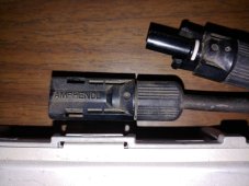
The panels make DC volts. The raw/wild DC goes to the junction box “internally” with probably some diodes and maybe a parallel connection (probably not) and the output wires are feeding microinverters that take the DC and make it AC voltage. That is effectively the “panel output” but the DC wires between JB and micinverts can be used to measure panel efficacy.
Ok, thanks for confirming that. I thought I might be being told something else
")
.
>If you have good DC but no AC-out, then THAT indicates a likely bad microinverter.
Well, this is where I'm still in an unknown.
Since the inverters are grid connected, there is always 120VAC on each leg so I guess I need to measure the current. Since I should not disconnect and re-connect the panel while there is power from the inverter, it's not clear to me how I go about this. Sorry but someone explaining it face to face, I'd get it immediately but using text is making it a lot more complex than it actually is and will be once I know what I'm doing.
>If you have poor DC then it’s panel, JB, or cable/connector issues.
I can can test each panel once that meter I ordered gets here.
>Likely you’ll have good DC and a bad microinverter.
Still not clear how I can confirm the inverters are working or not since they are grid connected so always have AC on their output side.
As mentioned, some of them are making a really loud buzzing sound so I assume more have or are about to fail.
I also assume there is no fire hazard to worry about since the system is using heavy shielded cabling and the inverters are sealed in metal canisters. I'm assuming that because everything would have had to pass standards and I'm in a serious fire zone area.
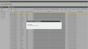
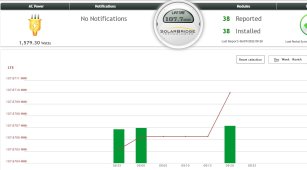
>Which is what I’m saying. Your charge controller and/or monitoring system is whacked
I must have missed something. I have DC to AC inverters. What charge controller are we talking about?
If someone still wants some pics from underneath, I can do that. It's just that they aren't going to show anything more useful then the docs I shared which clearly show how it's wired up.
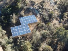
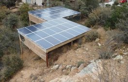
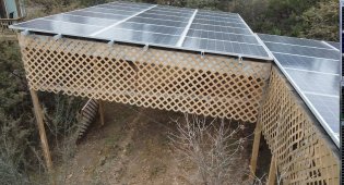
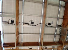
I forgot I had taken a little drone footage so see what trellis panels I needed to fix as they regularly break so here are some caps to show what I mean by canopy.
At the back, things are easy to reach, at the front of each section, it's one heck of a challenge as it is very steep rocky sand and very tall at around 16 feet at the high end.


 www.harborfreight.com