diy solar

diy solar

Do I need to do anything special to use individual inverters for individual circuits?

arielbalter

New Member
Joined
Apr 1, 2024
Messages
4
Location
Portland, OR
I tried searching the internet, and everything I found was about using inverters in parallel seemed to be for coordinating multiple inverters supplying to a single bus. I'm curious about using multiple inverters with different power ratings for circuits that will have different loads.

I'm building an all-electric, off-grid system for a tiny house. There are a few things that draw a lot of power intermittently: Induction burner, oven, on-demand water heater, etc. Everything else is low-power.

With a large inverter the draw would be far below the efficient range of operation the vast majority of the time. At least, I've found this image in multiple places on the internet, such as [here](https://www.e-education.psu.edu/eme812/node/738):
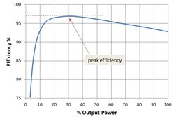
1712021398480.jpeg

Rather than a using a single 6000W inverter and only drawing enough power for lights, laptop, and refrigerator 90% of the time, I was wondering if I could, instead, use multiple smaller inverters in parallel (as shown below)? Also, since each inverter would have its own switch and fuse, I wouldn't really need a breaker panel.

This would not require coordination between the inverters. I don't see why it would, in principle, create an excessive load on the batteries compared to a single inverter at the maximum draw.

Am I missing something?


Code:
            +---------+                                                                 
      ------|         |---+------------------+                                          
 2.5A       |  300W   |   |                  |                                          
      ------|  120VAC |---------+            |                                          
            +---------+   |     |            |                                          
                          |     |            |                                          
                          |     |            |                                          
                          |     |            |                                          
            +---------+   |     |            |                                          
      ------|         |---+     |            |                                          
 2.5A       | 300W    |   |     |            |                                          
      ------| 120VAC  |---------+           ----                                        
            +---------+   |     |         ---------                                     
                          |     |           ----                                        
                          |     |         --------- 12 V                                 
                          |     |           ----                                        
            +---------+   |     |         ---------                                     
      ------|         |---+     |             |                                         
  15A       |  2000W  |   |     |             |                                         
      ------|  120VAC |---------+             |                                         
            +---------+   |     |             |                                         
                          |     |             |                                         
                          |     |             |                                         
                          |     |             |                                         
            +---------+   |     |             |                                         
      ------|         |---+     |             |                                         
  30A       | 4000W   |         |             |                                         
      ------| 120VAC  |---------+-------------+                                         
            +---------+
 
Last edited:
As drawn you could have a load of 550 amps on the 12 Volt battery, that is basically an impossible load to support.
 
As drawn you could have a load of 550 amps on the 12 Volt battery, that is basically an impossible load to support.
I was presuming a big enough battery bank. The theory works. The specifics may not. Good to note.

With the inverter wattages listed, I'd bump up the battery voltage to 24 at least.
 
That graph came from Victron.

Let's make sure we're not overly complicating things to pick fly turds out of pepper.

I have 10kW worth of inverters, and the vast majority of the time I'm pulling 90-150W of AC power.

When deciding to implement multiple inverters on separate circuits, it's very important to understand that big inverters burn big juice even when they're not providing power. Simply being on consumes power. Many have a low power mode, but they still burn more than you think they should, and equipment isn't always reliable when operated on them.

A true tankless on-demand hot water heater is almost foolish to choose in an off-grid setting.

Another restriction is that the inverters can't be connected to an AC source simultaneously.

As drawn you could have a load of 550 amps on the 12 Volt battery, that is basically an impossible load to support.

And this is an excellent point. If you need to pull 6000W, you need to be at 48V.
 
There are other considerations aswell, with say three parallel independant inverters, each with idle current just to be on, you may be losing more to idle than one inverter would lose to low efficiency.
I agree with @sunshine_eggo - it may be far better for your set up to avoid things like an on-demand HWT so the inverter can be sized smaller, and have just one.
I was not aware of that. Seems like I could get those specs and do that calculation.
 
So, let's set aside the HWT. I still have many standard household appliances that need to draw 8-20A for short periods of time intermittently: toaster oven, blender, electric kettle, 2x induction burner cooktop, small AC unit, etc.

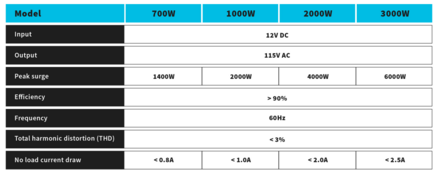
Tell me if I'm thinking about this the right way. A Renogy 2000W inverter RNG-INVT-2000-12V-P2 has the following idle loss:
1712028986855.png
So, the loss is about 12Vx2A = 2.4W or about 1.2% nominal output capacity. I looked at some other models as well. No-power draw seems to be in the 1-3% range depending on what bells and whistles the inverter has, and if it has charging duty.

1@ 300W inverter for receptacles only used for electronic devices etc.
1@ 700W inverter for refrigerator
3@ 2000W inverter for misc kitchen appliances
1@ 3000W inverter for AC
1@ 3000W inverter for cooktop

That total capacity is 9300W which would incur a continuous loss of 10-30W.

I looked at an EG4 6000XP Off-Grid Inverter that says it draws 50W in idle. And a Spartan Power 6600 Watt 48V 120/240V Pure Sine Wave Inverter Charger SP-IC6648 that draws 45W in low power mode. These are, indeed a bit more efficient than the simple lower-power inverters.

But, aside from when running the AC, they would be spending 80-90% of their time operating at 10% or less capacity.

Hold on a minute!

I just noticed that the graph from Victron truncated the y-axis! So, I'd still likely be operating at decent efficiency.

Hmmmm. This was an interesting exercise.
 
Hmmmm. This was an interesting exercise.

I've never quite seen anything like it. 8 inverters for a tiny house. You boggled parts of my brain that I didn't know existed.

Trying to imagine how much you'd really gain and at what expense/complexity.

Something else to remember... when you have low efficiencies with low numbers, the losses are low numbers too.

My 10kW of Victrons burn about 55W total... which pretty much adds to the 90-150W "background" loads. On a 3kW PV system, that's just background noise - about 8% of my total. That loss decreases the more I use stuff.
 
My understanding is inverters have an efficiency curve. It's possible running at 10% output is going to be the in the worst part of the curve, depending on the inverter.

Anyways, the others are right- take it from me, as someone who went with a 12V system: It's definitely not what you want for this kind of application. It would be far more sensible to go with fewer (maybe even just one) inverters on a 48V system.

It's also going to be a lot of 4/0 cables you will need to build or buy for all the different inverters- if you even get a big enough battery bank to support the amp draw. And to make it reasonably safe, you will need to fuse everything so that if one or two inverters go full tilt, you don't burn the entire building down. You're just running up against the hard limits of physics, too many amps. The solution is going up in voltage.
 
most power supplies operate most efficient at 40-60% but these inverters have a running wattage so you're probably wasting more power just by having them running than their efficiency loss if they were at 90%
 
I have a large and small inverter in my RV. They work fine together powering separate circuits and pulling power from the same battery.
They are tied onto separate branch circuits with separate transfer switches. With utility power all flows through, off grid they can be switched on as needed.

No reason 4, 6 or 12 would have any special issues.

I would definitely recommend battery at 48 volts or at least 24v with any inverter over 2000 watts.

Consider a small compressor water heater if concerned about efficiency. Will put 2x to 3x the BTU into the water per kWh vs resistance heat.
 
As drawn you could have a load of 550 amps on the 12 Volt battery, that is basically an impossible load to support.
Depends on setup. Multiple batteries will divide the load. The only place you could see the 550a would be the distribution point such as the common bus bar. From it to the separate inverters are just what they demand so all your wires can be sized based on individual inverters. Many people already run 2 inverters to get split phase (even if in one AIO enclosure) or 2 or more to get single phase parallel at a higher total watt rating. Some run 3 to get 3 phase.

No reason that you can not run multiple inverters from a common source. I do not think it is worthwhile based on idle load but it could be worth while to gain either more circuits or a heavy load (perhaps a 240vAC that you use rarely but still would like to power). I presently run 2-3kW AIO's powering separate 120vAC circuits in my home that I have a transfer switch to allow 1 unit to power all (but at reduced loading ability) if PV supply is inadequate to cover idle draw of the 2. I am thinking of adding a dedicated 240vAC split phase inverter (not AIO or charger) just to power a few 240vAC loads I have.
 
I think I would just stick with a single inverter or at most 2, then just add another battery to compensate for the waste - much cheaper than all those inverters.

And two thumbs up for 48v for all of it.
 
If we can assume the PV is limited in this set up, best to look at the very lowest idle current draw possible for your system, since the trick of just adding extra PV to offset idle consumption may not be available to you. Soooo... at the risk of @sunshine_eggo seeing the endorsement, Victron has some of the lowest idle current equipment out there.
 
So, let's set aside the HWT. I still have many standard household appliances that need to draw 8-20A for short periods of time intermittently: toaster oven, blender, electric kettle, 2x induction burner cooktop, small AC unit, etc.

Tell me if I'm thinking about this the right way. A Renogy 2000W inverter RNG-INVT-2000-12V-P2 has the following idle loss:
View attachment 206417
So, the loss is about 12Vx2A = 2.4W or about 1.2% nominal output capacity. I looked at some other models as well. No-power draw seems to be in the 1-3% range depending on what bells and whistles the inverter has, and if it has charging duty.

1@ 300W inverter for receptacles only used for electronic devices etc.
1@ 700W inverter for refrigerator
3@ 2000W inverter for misc kitchen appliances
1@ 3000W inverter for AC
1@ 3000W inverter for cooktop

That total capacity is 9300W which would incur a continuous loss of 10-30W.

I looked at an EG4 6000XP Off-Grid Inverter that says it draws 50W in idle. And a Spartan Power 6600 Watt 48V 120/240V Pure Sine Wave Inverter Charger SP-IC6648 that draws 45W in low power mode. These are, indeed a bit more efficient than the simple lower-power inverters.

But, aside from when running the AC, they would be spending 80-90% of their time operating at 10% or less capacity.

Hold on a minute!

I just noticed that the graph from Victron truncated the y-axis! So, I'd still likely be operating at decent efficiency.

Hmmmm. This was an interesting exercise.
12V*2A = 24w (1.2%) not 2.4w

1-3% of 9,300 is 93-297w continuous.
 
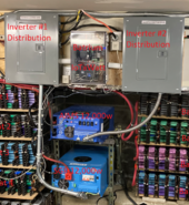
I have 2 x 12,000w inverters that power separate circuits. And indeed, the efficiency rises ~7% (78% -> 85%) as I load them ~40% and greater. In winter/low PV I only run 1 to keep efficiency up as I don't run as many circuits to use all the PV. Each inverter goes to it's own distribution panel but they are cross-wired so that 1 inverter can run both in either direction.
1712103755556.png
So yes, one can have multiple inverters from the same battery powering independent circuits.... one could do 10 inverters of 2000w each and even cross-connect the circuit distribution boxes to offer manual load management adjustments but the complexity rises as it's easy to temporary pull unexpected hi power from any 1 circuit.

Take my kitchen for example.... it has 2 x 20a circuits but on either one of them there are counter top plugs and microwave and refrigerator and k-cup and toaster ovens. Depending on what my wife is doing, power can go to the max with no notice or be low most of the time - very hard to 'manually' optimize at this level.

Also, I feed my inverter power via ATSs and having 10 inverters would required at least 10 ATSs to make this automatic with grid assist.

I did the 2 x inverters because I couldn't find a single cheap 24,000w. The manual efficiency game I play of falling back to 1 inverter in winter is more of a hobby than something I'd recommend as a deliberate design. The easier route might be to add few panels to make up for efficiency losses.
 
Last edited:
Back
Top