diy solar

diy solar

Silicone wire on your solar system setup

Its exactly why my own home solar system is 100 volts nominal dc. Thirty lithium cells.
5Kw inverter, or solar is only fifty amps dc maximum.

Some guys here ar talking about HUNDREDS of amps, and that just boggles my mind.
 
Here is a chart of wire size and current ratings for "chassis" and "power distribution".
https://www.powerstream.com/Wire_Size.htm

Interesting chart, with "skin depth" or frequency at which full cross-section of wire is useful.

What they left out was insulation temperature rating and ambient temperature.

Still, there is a limit according to that table for chassis wiring and it's not as high as I was expecting, but it's not related to the insulation material, so I can get away with a 25mm2 PVC wire for very short less than 1m lengths.

Notes relating to the chart say,

"The Maximum Amps for Chassis Wiring is also a conservative rating, but is meant for wiring in air, and not in a bundle."

Their 190A ampacity is close to NEC 195A for 90 degree wire, 30 degrees ambient, bundle of up to 3 current-carrying conductors:


For chassis wiring, their 283A figure for 2/0 is between NEC free air rating of 300A for 90 degree wire and 265A for 75 degree wire. That could be for somewhat higher temperature inside chassis. (283A/300A)^2 = 0.89 times as much power and temperature rise.
90 degree - 30 degree = 60 degree rise for standard figures. 60 degree x 0.89 = 53 degree rise.
90 degree - 53 degree = 37 degree ambient.

I think their 283A figure for 2/0 single wire in free air would work in a 37 degree C cabinet, with wire reaching 90 degrees.


According to this guide, only "heat resistant" PVC is good to 90 degrees C. Other types 70 degrees C. So check your PVC rating.


NEC ampacity rules allow a short (< 24") length of wire to be in a conduit nipple containing large number of wires without derating maximum current. Not mentioned is whether the wire has to extend many feet to in one or both directions beyond the nipple, or can immediately connect to a terminal. I think if it landed in a terminal just after exiting the nipple, whether this was a safe exception or not would depend on thermal path and heatsinking provided by that terminal and device.

Other than when there is a thermal path to some heatsink, I don't think "short length" is an excuse to exceed ampacity and temperature rise. Battery could serve as heatsink; it has a much larger surface area than short wires.
 
Interesting chart, with "skin depth" or frequency at which full cross-section of wire is useful.

What they left out was insulation temperature rating and ambient temperature.


Notes relating to the chart say,

"The Maximum Amps for Chassis Wiring is also a conservative rating, but is meant for wiring in air, and not in a bundle."

Their 190A ampacity is close to NEC 195A for 90 degree wire, 30 degrees ambient, bundle of up to 3 current-carrying conductors:


For chassis wiring, their 283A figure for 2/0 is between NEC free air rating of 300A for 90 degree wire and 265A for 75 degree wire. That could be for somewhat higher temperature inside chassis. (283A/300A)^2 = 0.89 times as much power and temperature rise.
90 degree - 30 degree = 60 degree rise for standard figures. 60 degree x 0.89 = 53 degree rise.
90 degree - 53 degree = 37 degree ambient.

I think their 283A figure for 2/0 single wire in free air would work in a 37 degree C cabinet, with wire reaching 90 degrees.


According to this guide, only "heat resistant" PVC is good to 90 degrees C. Other types 70 degrees C. So check your PVC rating.


NEC ampacity rules allow a short (< 24") length of wire to be in a conduit nipple containing large number of wires without derating maximum current. Not mentioned is whether the wire has to extend many feet to in one or both directions beyond the nipple, or can immediately connect to a terminal. I think if it landed in a terminal just after exiting the nipple, whether this was a safe exception or not would depend on thermal path and heatsinking provided by that terminal and device.

Other than when there is a thermal path to some heatsink, I don't think "short length" is an excuse to exceed ampacity and temperature rise. Battery could serve as heatsink; it has a much larger surface area than short wires.
I was told by my inspector that the nipple exclusion is for connecting between troughs or passing between walls. A nipple cannot have fittings on them and count as a nipple for the exclusion. The nipple rule only applies when the ends of said nipple are free.
 
Best use for silicon insulated wire is for the BMS sense leads. It self fuses in the event of a direct short circuit without catching on fire in the process.
Yes. Although I think of high temp insulation as to be used around a hot environment such as a sensor inside an oven or connected to a heater.
 
Charts like these can be very helpful, and definitely better than nothing.
However, industry standards and precise legal codes vary throughout the world and it can all become rather confusing.
There is no single correct answer to where the exact safe limits lie.
Engineering standards in general are based on a vast amount of historically accumulated data and experience often learnt from past disasters and failures. But in the end, its up to you to decide. Are you feeling lucky ?
 
whats a difference between a busbar and a wire, but it’s insulator.

exactly, is there an ampacity rating of pure copper busbars?

In my case, I got for free 2m of copper bars, one is 20x3mm (60mm2 section) and the other 20x4mm (80mm2 section) and I'm going to use those as much as possible, but of course, I need wires for flexibility since the system will be mounted in an RV and I'd like to save as much money as possible on wires, while still building a safe and efficient system. Hence why we are here asking questions and learning stuff to optimize our systems.
 
I´ve Been down that rabbit hole before.
Silicon Wire Is really nice and flexible, not only it resist temperature up to 200celcious, but also insulate its surrounding from that heat. Those are great attributes and highly sought after in some applications. Like Battery Making.

I also tested running a 1600Watt 12v inverter with a single 8AWG. It works, but with 140 Amps going through, the wire just gets too hot for the touch. >60c.
You can see BMS that come with leads are usually Silicone wire. Because they allow the flexibility for bulding inside a battery case.

There is one application that I use Silicon Wire allot, which is Short Burst of Amps to Crank an Engine. In that situation, the exposure to high Amps is so Short, that the Silicone Wire Virtually acts like a Busbar, for a fraction of a second.

Remember that when Calculating the AWG size you need you have to take into account:
  1. Insulation rating in Celcious: 60c, 90c, 105c
  2. Continous Amps going through AND
  3. Lenght of wire
  4. Material: Copper of course

So, there are dozens of tables showing you ampacity based on diferent factors, most are a variation of the above.

So that is why a 10AWG DC 1inch for interconection in batteries is rated @50Amps and at 28 feet in your house AC Breaker is rated @ 20 Amps.

My rule of thumb with silicone wire is Derate it 50% and then double up the wire. (my runs are never over 2 feet).
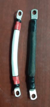
I cover them with Braided Fiberglass sleeve


This is my conlusion, based on my necesities.
That is my grain of salt. Hope it helps someone.
Regards


2 X 8AWG Silicon Wire on each interconnect. Braided Fiberglass sleeve.
1655316781265.png


1655316558301.png
 
Last edited:
If you're going to push wire then silicone, or teflon would be ideal.

But don't go by what's acceptable by hobby. In hobby the high currents are what 10-15mins at most? Also these hobby cars, and planes are used outside so when they go ablaze It's outside not in your house while you sleep.

Be safe!
 
Can you push conductors to extremes - yes.
Should you push conductors to the extremes - absolutely not.
 
Yes, bus bars are rated by size and material made from.
Also, buss
I´ve Been down that rabbit hole before.
Silicon Wire Is really nice and flexible, not only it resist temperature up to 200celcious, but also insulate its surrounding from that heat. Those are great attributes and highly sought after in some applications. Like Battery Making.

I also tested running a 1600Watt 12v inverter with a single 8AWG. It works, but with 140 Amps going through, the wire just gets too hot for the touch. >60c.
You can see BMS that come with leads are usually Silicone wire. Because they allow the flexibility for bulding inside a battery case.

There is one application that I use Silicon Wire allot, which is Short Burst of Amps to Crank an Engine. In that situation, the exposure to high Amps is so Short, that the Silicone Wire Virtually acts like a Busbar, for a fraction of a second.

Remember that when Calculating the AWG size you need you have to take into account:
  1. Insulation rating in Celcious: 60c, 90c, 105c
  2. Continous Amps going through AND
  3. Lenght of wire
  4. Material: Copper of course

So, there are dozens of tables showing you ampacity based on diferent factors, most are a variation of the above.

So that is why a 10AWG DC 1inch for interconection in batteries is rated @50Amps and at 28 feet in your house AC Breaker is rated @ 20 Amps.

My rule of thumb with silicone wire is Derate it 50% and then double up the wire. (my runs are never over 2 feet).
I cover them with Braided Fiberglass sleeve


This is my conlusion, based on my necesities.
That is my grain of salt. Hope it helps someone.
Regards


2 X 8AWG Silicon Wire on each interconnect. Braided Fiberglass sleeve.
View attachment 98709


View attachment 98708
5. The environment where the wire is used.
6. Conduit derating.
7. Multiple conductors in proximity derating.
Ampacity is ampacity. Additional insulation heat tolerance is a calculation factor, not an absolute capacity number.
I don’t care WHAT the ampacity rating of the insulation is, when feeding an inverter, voltage drop is lost capacity.
Absolutley
Silicone wire just gives the DIY or beginner more Buffer in the case there was a miscalculation.

Aditionally, Silicone delay combustion or inhibit fire spread.

https://www.researchgate.net/public...itions_via_insulation_resistance_measurements
 
Back
Top