diy solar

diy solar

Silicone wire on your solar system setup

Here is a review of a 8 awg silicone wire at over 100a under a long duration of time..
A youtuber saying something does not make it so.

Yes. 8Awg wire with silicone high temp wire will survive 100A for a short time without melting…

Certainly not ideally. There will be a lot of wasted watts due to heat.

There will be a lot of voltage drop causing MORE heat in the wire.

In a 100Ah battery it won’t matter, because the battery will run out of juice before the wire melts.
 
Here is a review of a 8 awg silicone wire at over 100a under a long duration of time..
Did you read the comments under the video? He responded that he has doubled the wire, or changed to 6Awg in his batteries.

Oh… and continuous load means 3 hours or more… not 15 minutes.

Please trust us. Don’t waste your money and safety on wire that is undersized for the application.
 
According to this table 200C rated 6AWG wire can only do 165A


I actually use some 6AWG silicone wire in my system. 100A continuous is about the most I'd use it for.
 
Last edited:
umm no 6 AWG is NOT rated for 300Amps power transmission. It could handle it For a microsecond maybe at a foot long.

Well, actually a 1 mil wire can handle 1000A for about a microsecond. With 1000V applied.
That's 1 Joule expended in 1 microsecond.
(Admittedly, a very special-purpose application)

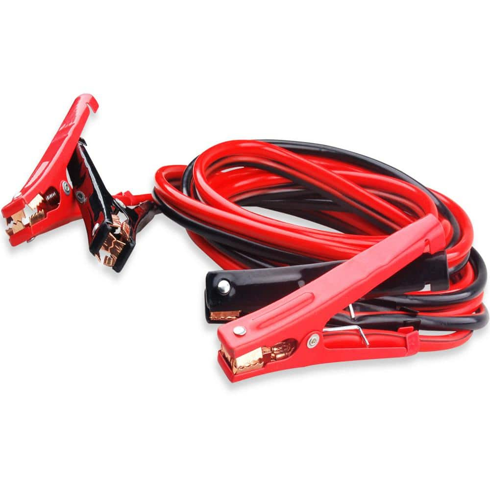
6 awg as a jumper cable could handle 300A for cranking.


This one says 200A 6 awg, but that's aluminum:


Home Depot is less conservative than Harbor Freight. 300A 6 awg "CCA" which means aluminum)

 
I do hope the OP listens to our advice. Wasting money is never a good idea.


Size the CONDUCTOR for best continuous use loads… use the insulation for overload protection…

10W of waste… um… no…

#6 at 300A would be wasting far more than 10 watts…

Somebody please do the math.
10W of waste? More like 0.2W per foot.

Edit: actually it's about 0.2019W/ft at 300A and 200C conductor temperature
 
Last edited:
10W of waste? More like 0.2W per foot.

Edit: actually it's about 0.2019W/ft at 300A and 200C conductor temperature
Just the voltage drop alone for 1 foot @300A with 8 AWG is 0.21V. 300Ax0.21V=63W

With 6AWG it's 0.14V and that would be 42W
 
Just the voltage drop alone for 1 foot @300A with 8 AWG is 0.21V. 300Ax0.21V=63W

With 6AWG it's 0.14V and that would be 42W
At 200 degrees Celsius 6AWG copper has a resistance of 0.673 Ohms/1000 ft.

300 * 0.673/1000 = 0.2019 W

Edit: Nvm that's volts lol. Actual power is 300^2 * 0.673 = 60.57W/ft
 
Last edited:
Just today I was putting 25Arms through 16' of 20 awg silicone insulated wire. Took 10Vrms to do it. 60 Hz.
Don't think was IR drop in the wire, rather inductive coupling to the core I wrapped it around. 60 turns, and solid core not laminated, so I figure 1500A of eddy current.
It got hot fast! (core was hotter than the wire.)
 
....He responded that he has doubled the wire, or changed to 6Awg in his batteries....
I think he switched to 6awg AND doubled the wires. Plus, his batteries are rated only for 110a. That's ~55a per 6awg wire, I didn't check a chart, but that sounds within most "code" limits to me.
 
I think he switched to 6awg AND doubled the wires. Plus, his batteries are rated only for 110a. That's ~55a per 6awg wire, I didn't check a chart, but that sounds within most "code" limits to me.
Mine don't even feel different from ambient temperature at 50A. 55A should be fine.
 
Well, Well,

I Stand in between you guys.

@sirslayer I would take the max at half the rating. 6awg = 150 A

I have tested extensively silicone 8 awg up to 150 amps, and I would not go past 100 amps which is half its rating.
It gets too hot, meaning resistance is High. Ohms Law. In short runs < 6” its not a problem. but after that, the resistance increases exponentially.
I tested with a milli Ohms meter. I use silicone for all my battery builds.
check this video for resources

Video 2
 
High temperature cable is specified only for use in a high temperature environments, for example wiring in the control part of a stove or furnace, or maybe welding cable that might be accidentally draped over hot metal. Perhaps in the confined space of an ship engine room or generator, that type of thing.
In aircraft for example, fire proof (teflon) insulation is required by the FAA for fairly obvious reasons, not so you can fly through the sky running with red hot wires.

You do not specify high temperature insulation for a reading lamp just so really ultra thin copper can be used.

If your actual battery cells run at 200 degrees, you have a problem that goes way beyond needing to use high temperature rated wire.

Fine stranded cable only has one application, flexibility. Welding cable, and things like multimeter probes need very flexible cable.
Wiring sitting on top of a battery probably is better stranded, but it certainly does not need to have thousands of hair like strands to do the job.
Besides the ultra flexible stuff is damned expensive, and so is high temperature silicon rubber or teflon insulation.

If spending money uselessly is your thing, then go for it.
 
I agree with most of the stuff that's been said here. I believe the current rating of a wire (or ampacity) is a condition that has to be met together with the recommended voltage drop, for example under 3-4% but I prefer to be under 1-2% for efficiency.

There is something I don't understand though:
if the voltage drop of a given situation is low enough (short wire) but the current is high, most wire calculators will tell you to use a bigger wire because of the common amp rating of regular PVC, but if using silicon wire, consider the higher amp rating could we chose the wire by the voltage drop?

I'll give an example of my planned system, 24V battery with 2400W inverter, considering power factor and some headroom let's assume 150A max. If I have a very short wire run from the battery to the busbar, for example 0.5m (1.6ft), the voltage drop with a 16mm2 (5awg) wire is only 0.2v or 0.8% which is very efficient, since usually 2-3% voltage drop is recommended. But if I use a wire calculator, since most consider the current rating of regular PVC they advise 95mm2 (3/0-4/0 awg) which of course will have a voltage drop of only 0.16% and seems way overkill for such a short run.
If the voltage drop is so low, there's not enough power loss and so no heat generated, so why does a PVC wire have a max amp rating that doesn't make sense for very short wires? Is it maybe because most of the situations have wires much longer and so short wires are not considered?

I was considering going up a size and using a 25mm2 wire (about 3awg) and getting the silicone one even if it's more expensive just to meet the amp rating, but in my mind for such a short run that wire will never see those temperatures and so a regular PVC should be fine.
 
Yes you are quit right.

Published current figures need to be interpreted and understood. Quite often there are two current ratings for the exact same wire, one is often called "chassis wiring" for short wiring runs INSIDE equipment. Then there is "power transmission" which is a guide only for much longer wiring runs.

For example domestic cable for wiring within buildings might assume a cable maximum length of a hundred feet or less. Larger buildings will have sub power boards, so it would be unusual to exceed a hundred feet between sub board and power final outlet. So 15 amp rated building cable will be fine for that type of application.

But if you wanted to run a couple of hundred yards of feeder cable BETWEEN different buildings, that same cable would very likely have an unacceptable voltage drop at the full rated 15 amps.

Going the other way, you might have a big control panel for a large machine that has motors, relays, circuit breakers, switches. All the wiring is in a confined cubicle and quite short. So you can run wiring at a higher current density, because voltage drop is simply not an issue.
Here is a chart of wire size and current ratings for "chassis" and "power distribution".
https://www.powerstream.com/Wire_Size.htm

The manufacturers rating will always be safe for very short runs, but if serious distance is involved its always wise to do some voltage drop calculations.

Another thing to keep in mind. If it works out that there might be a six percent voltage drop. To decrease that to only a three percent voltage drop will take twice as much copper to do it, and that gets expensive very fast. Cable at least twice as expensive for three percent gain.
That might be a bargain, or maybe not. Its up to you.
 
Best use for silicon insulated wire is for the BMS sense leads. It self fuses in the event of a direct short circuit without catching on fire in the process.
 
@Warpspeed Thanks, that makes perfect sense. Another example would be the traces on a PCB like on the BMS. They are very thin but still can carry the maximum 200A the BMS is rated for because they are very short.

Still, there is a limit according to that table for chassis wiring and it's not as high as I was expecting, but it's not related to the insulation material, so I can get away with a 25mm2 PVC wire for very short less than 1m lengths.
 
Another thing to keep in mind. If it works out that there might be a six percent voltage drop. To decrease that to only a three percent voltage drop will take twice as much copper to do it, and that gets expensive very fast. Cable at least twice as expensive for three percent gain.
That might be a bargain, or maybe not. Its up to you.

Of course, that makes perfect sense, and it's why in most houses here in Europe they use 1.5mm2 for 9A circuits and 2.5mm2 for 16A circuits, without accounting for lengths and voltage drop. Even if it's a percentage a 6% drop on a 230V AC vs a 24V DC is much different, because once multiplied by the current, the power to dissipate is much different.

So I think for short runs between the electrical system, a <1% drop is better for safety and efficiency, but for a device far away that only consumes 5W a 5% drop is probably a none issue.
 
Yes indeed !
A 6% drop at 240v becomes a breathtaking 60% drop at 24v.

Going to a higher voltage lower current dc system, makes an absolutely huge difference to efficiency and wiring requirements.
 
Yes indeed !
A 6% drop at 240v becomes a breathtaking 60% drop at 24v.

Going to a higher voltage lower current dc system, makes an absolutely huge difference to efficiency and wiring requirements.
haha no I meant 6% at 240V vs 6% at 24V. It's a percentage so the one at 24V will be a lot less. But considering the 24V will have a much higher current, effectively 10 times as much for the same load, the power dissipated in the wire will be much more.
 
Back
Top