diy solar

diy solar

CT current sensors connection options on a Solark12k

offgrider

New Member
Joined
Jul 20, 2020
Messages
65
I have 200amp POCO service so I got the larger CTs for the solark. The solark wiring diagrams shows to connect the CTs to the house mains panel input from the POCO meter. But my setup is a bit different. My meter on the side of my house has 1 input from the POCO, but 2 outputs to feed different panels. One panel is on the outside of the house next to the POCO meter. This outside panel has breakers for the ACs, polebarn, entry gate, etc. The 2nd panel (house mains panel) is in the garage next to my critical loads panel and the inverter.

My electrician says theres no good way to get both outputs of the POCO meter (that feed my 2 panels) in these CTs. What do I do? Will I be missing out on something if I put the CTs on the house mains panel? Will that "miss" something with that outside panel?

Or do I want to just put these CTs on the "outside" of the POCO meter? ( between the meter and the POCO grid itself)?

Also, what all exactly can these CTs do? I can easily understand how they can measure the amount of power flowing (basic electro/magnetic field induction) but can they actually measure which side is producing and consuming?

TIA
 
Last edited:
A picture would be really helpful. If I am getting you correctly then yes you could put it before the meter if you have no other choice.
 
Code:
(POCO)----(Meter)-----(HousePanel)----(SolArk)----(CritLoadsPanel)-----(Kitchen, Wellpump, etc)
            |                 |
            |                 |------(House Loads)
            |
            |------(OutsidePanel)----(HVAC, PoleBarn, Entry Gate)
 
Problems with CT setups are usually wiring polarity errors.

Reversing output sense wires
Putting power cable through the CT transformer from wrong side.

In order for CT sensing to determine the direction of power flow the phasing has to be correct. For example, reversing the sense wires makes the inverter think it is consuming from grid instead of pushing to grid. Same if you put the CT donut on the power cable in reversed orientation.

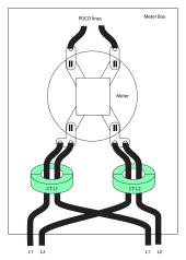
If your meter has two outputs you need to sense the lines from POCO side of meter. You should be able to do this in the meter box. You own the meter box, its socket, and any cables from meter to weather head. The POCO owns the meter. A licensed electrician is allowed to open and work in your meter box. The electrician can pull the meter but he cannot cut incoming power from POCO transformer. If he is good he should be able to place clam type CT sensors on POCO input wires without calling POCO to remove power from pole transformer.

If you are lucky the meter socket has two terminal pair adjacent with the two cables coming out of each L1 & L2. If CT loop is large enough to run both cables through it you can put it on output side of meter. I would expect the electrician should have already checked for this.

Just check that everything is working right before you let electrician leave. If he is not real familiar with CT sensors he could very easily put through wires in wrong orientation side of CT donut. You can fix the problem by reversing the CT output sense leads at inverter input. In this case, two wrongs make it right.
 
Last edited:
...If your meter has two outputs you need to sense the lines from POCO side of meter....

...If you are lucky the meter socket has two terminal pair adjacent with the two cables coming out of each L1 & L2. If CT loop is large enough to run both cables through it you can put it on output side of meter. I would expect the electrician should have already checked for this.
ok this is just the info I needed. Ill let him know when he comes back tomorrow that he can do in on the POCO side of the meter.
Thanks all this is great!
 
Just check that everything is working right before you let electrician leave. If he is not real familiar with CT sensors he could very easily put through wires in wrong orientation side of CT donut. You can fix the problem by reversing the CT output sense leads at inverter input. In this case, two wrongs make it right.
Sol-Ark already has a built in feature that once turned on will automatically reverse the CT sensors internally if needed.
 
Sol-Ark already has a built in feature that once turned on will automatically reverse the CT sensors internally if needed.
well thats pretty neat... now there are quite a few combinations to do this though; with 4 wires and 2 donuts that each can go in 2 different directions... can the solark figure each bad combo out and solve it?
 
well thats pretty neat... now there are quite a few combinations to do this though; with 4 wires and 2 donuts that each can go in 2 different directions... can the solark figure each bad combo out and solve it?
As far as I know yes but you can cal Sol-Ark and double check.
 
In theory, I believe you could also splice in another set of CT"s, like the SUN limiter inverter guys are doing, then put a set on each panel, but the ideal way to do it is as outlined by the other guys.
 
As far as I know yes but you can cal Sol-Ark and double check.
I called solark, that functionality for autosense only functions if you have batteries, and my batts (and bms) just arent ready yet.

turns out that my electrician did have to put the CT's between the meter and the POCO, and ugh, he pointed them towards the meter/house, not towards the poco. and when I powered the system up today, the display with power flow meters didnt make ANY sense. so I powered it all down and for the CTs I swapped the polarity between pins 3&4 and then between pins 5&6. the book says to put the whites on 3&5 and the blacks on 4&6. So I swapped that and did blacks on 3&5 and whites on 4&6. then when I powered is back up the 4 meters on the inverter made much more sense - It was starting to get dark and so at that point it showed PV only generating a few hundred watts, and the grid supplying around 3KW and the load absorbing 3KW. Then I hit the garage door opener and the grid showed me buying 4kw and the load showed consuming 4KW. ok much better.

BUT THEN so we left and came back and its all dark, the inverter is all still powered up and everything, but says OFF, and all 4 meters show 0KW even though there are obviously loads going on in the house and am buying from the grid. whats up with that? does the system just not do any reporting at all unless the PV is generating at least some small amount of power or what?

in any event, Im SUPER STOKED here that I got a working plant here, I was generating around 8KW earlier today this is so incredibly cool, thanks all so very much for all the assistance over the past year. you too Will you're freaking awesome.
 
Glad it worked out.
Did you check the menu option to let it know you have no batteries connected? So long as grid power is running through the inverter it will remain powered even if no PV or Battery is connected.
 
yes there were 2 boxes to uncheck on the batt setting. so yea the inverter is powered up and the screen lets me navigate around and all, but just odd that it says OFF on the screen and all 4 meters show zero even though we're obviously running things in the house.
 
Sol-Ark already has a built in feature that once turned on will automatically reverse the CT sensors internally if needed.
The only caveat to this is you must have batteries for this feature to work.
 
yes there were 2 boxes to uncheck on the batt setting. so yea the inverter is powered up and the screen lets me navigate around and all, but just odd that it says OFF on the screen and all 4 meters show zero even though we're obviously running things in the house.
I have never tried this but it makes no sense to me that it needs battery power to operate the CT censors if the rest of the unit is powered up. And you say that Sol-Ark said this was to be expected? If not I would call and clarify it.
 
The only caveat to this is you must have batteries for this feature to work.
Are you sure? I installed mine myself so I made sure they went in right and I did not need to turn on the Automatic CT polarity option on. Are you also saying that if he had installed them correctly he would be getting a grid power reading on the screen?
 
Are you sure? I installed mine myself so I made sure they went in right and I did not need to turn on the Automatic CT polarity option on. Are you also saying that if he had installed them correctly he would be getting a grid power reading on the screen?
All I am saying is you need batteries to do the auto learn function. Here's a clip from the manual.
 

Attachments

  • Untitled.png
    Untitled.png
    92.5 KB · Views: 9
All I am saying is you need batteries to do the auto learn function. Here's a clip from the manual.
Well we do know that it does not unlearn the info when powered down so I think it's safe to assume that no matter how you set them up you will not get a reading without a battery connected. It really sounds odd to me.
 
as soon as the sun started shining today, the inverter panel changed from showing OFF on the display and started showing power flow between PV, grid, and my home loads. (nothing on the batts, the 4th meter, since I dont have them connected yet)
 
as soon as the sun started shining today, the inverter panel changed from showing OFF on the display and started showing power flow between PV, grid, and my home loads. (nothing on the batts, the 4th meter, since I dont have them connected yet)
Yes it should come back on when PV is back on but I still don't understand why it needs batteries to show Current flow from the Grid. Anyway I guess that is just how they designed it.
 
Yes it should come back on when PV is back on but I still don't understand why it needs batteries to show Current flow from the Grid. Anyway I guess that is just how they designed it.
When it does the test it back feeds the grid from the batteries. It only does a couple hundred watts for 2 or 3 seconds. I guess that is how it can tell which line is which.
 

diy solar

diy solar
Back
Top