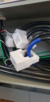
With dual Sol-ark 15k install and 400a grid service, is it ok to parallel a pair of CTs (per leg) into the master inverter? In other words, my grid line has two 4/0 wires per leg going to the meter for 400a service. Can I put a CT around each of these wires and then parallel them together at the master input? The CTs I got with my 15ks are too small to fit two 4/0 wires, but they can fit a single 4/0. I know larger CTs are available from Sol-ark, but if possible I'd like use the 4 I already have instead of ordering larger ones....
You are using an out of date browser. It may not display this or other websites correctly.
You should upgrade or use an alternative browser.
You should upgrade or use an alternative browser.
Ok to parallel CT sensors on dual Sol-Ark 15k install?
- Thread starter gmbeihl
- Start date
DIYrich
Solar Wizard
Seems like it would work. The CT's would add. I would ask Sol-Ark. They are responsive.
cooldog
New Member
- Joined
- Jun 5, 2020
- Messages
- 8
I have a very similar setup, and I called Sol-Ark for direction. The first-line tech said no, but I ended talking to their engineer and he said yes, I should put them in parallel as you described.With dual Sol-ark 15k install and 400a grid service, is it ok to parallel a pair of CTs (per leg) into the master inverter? In other words, my grid line has two 4/0 wires per leg going to the meter for 400a service. Can I put a CT around each of these wires and then parallel them together at the master input? The CTs I got with my 15ks are too small to fit two 4/0 wires, but they can fit a single 4/0. I know larger CTs are available from Sol-ark, but if possible I'd like use the 4 I already have instead of ordering larger ones....
BlueMarblePA
Solar Enthusiast
I have a single solark 15k going to one of my two 200amp panels. I was also hoping to measure loads for both panels for my 400amp service. Did this work for you?With dual Sol-ark 15k install and 400a grid service, is it ok to parallel a pair of CTs (per leg) into the master inverter? In other words, my grid line has two 4/0 wires per leg going to the meter for 400a service. Can I put a CT around each of these wires and then parallel them together at the master input? The CTs I got with my 15ks are too small to fit two 4/0 wires, but they can fit a single 4/0. I know larger CTs are available from Sol-ark, but if possible I'd like use the 4 I already have instead of ordering larger ones....
cooldog
New Member
- Joined
- Jun 5, 2020
- Messages
- 8
Right now, I can't say if the data I'm seeing is correct or not. Solar Assistant is showing a negative value for the CT Power, even though they absolutely are installed the correct direction. I'm still juggling so many things and changes all at once ... I may not know for a while.@cooldog
Have you tested out the parallel CT sensors with your 15K? Did it work as expected? Thanks!
I'm probably going to revert to PVPro for a few days as I mess with my batteries, and I'll see what data I get from it. I'm not 100% confident that Solar Assistant is interpreting things correctly.
But it was an engineer, not the support guy, and I made certain that he understood what I was doing and what I needed to have happen.
I talked to Sol-Ark today at length and they do not recommend paralleling CT sensors at all. Very unfortunate, but that is what they told me. They cannot say how accurate or inaccurate it would be so they don't think it is a good idea.
I don't need to use zero export mode so accuracy isn't terribly important, but if the numbers aren't reliable there isn't a lot of point to doing it.
I am going to be net metering, so CT sensors are required (I don't understand why, unless you have set the export limit which I won't, but it is what it is), so I will set up the CT sensors on mains into the panel the Solark is backfeeding and maybe I will set up an Emporia monitor on the other panel and do the math myself.
I am sort of tempted to get a second pair and parallel them anyway to see how well it works, but they only sell 15/16" 200A CTs, while the 15K comes with 1-3/8" CTs. If the parts aren't identical they are very unlikely to add together properly.
I would love to hear from anyone who has/is trying it and can put a clamp meter on the wires to assess the accuracy of the CTs in that configuration.
Thanks
Be advised that the circuitry in the Sol-Ark that is reading the values on the CT wires has a limitation on how much it can measure! On a 3 phase install we were limited to 40kw total, measuring 3 phase. That came out to around 116A..... so I am pretty positive that in a regular 120/240 split phase setup, you actually won't be able to measure anything over 116-ish amps. I had asked them about using 3rd party CT's with 6000:1 ratio to be able to measure (theoretically) 3x the power. But their response was that they don't recommend using CT's other than theirs.... I was a bit disappointed, as we are trying to measure loads coming off a total combined 90kw of generators! (2x 45kw in parallel.)
Just figured this might be of interest to anyone with this 400A service scenario. We have this scenario coming up as well, and I'm not sure exactly how we will handle it, so if anyone has advise, I'm open to suggestions. Lol
Just figured this might be of interest to anyone with this 400A service scenario. We have this scenario coming up as well, and I'm not sure exactly how we will handle it, so if anyone has advise, I'm open to suggestions. Lol
Maybe what I need to do is independently measure the current of each CT separately when not attached to the sol-ark and compare to the sum of the currents when both are connected to the sol-ark in parallel. If they are close, then I would think it is accurate enough. Otherwise, maybe they are backfeeding each others' secondaries and current is being lost that way. I would be surprised if the total current in parallel is more than the sum of the individual currents when connected separately.
Interesting. They do sell 400A CT sensors for the 15K, so it is probably OK to use theirs and they can say what ratio setting to use.

These are the 600A ones that they sell. They are big enough to run a number of large cables through them!

I don't remember the size of those wires, but for some reason I'm thinking maybe 2/0 copper or something like that. If you look closely at that picture, you will notice that on the CT it says 600A/300mA. That is a 2000:1 ratio, same as the smaller ones that come with the 12k or 15k units. Basically, all CT's from Sol-Ark are that ratio.
If 40kw is the max we can measure at 120/208V 3 phase, that gives us 40,000/208V=192.3/1.73 (for 3 phase)= 111A. So with a CT ratio of 2000:1 we go 111A/2000 = 0.0555A. So, the Sol-Ark circuitry maxes out at 0.0555A of current..... Theoretically, I would think paralleling 2 CT's should just add the mA together, and should work. But you will still ultimately be limited to 111A of total current with that CT ratio.
I think (someone correct me if I'm wrong here.) that using a CT ratio of, say, 6000:1 would yield 1/3 the mA of current at any given A flow through the CT's, therefore tripling the A limit that is measurable to 111x3=333A. However, I have yet to get the blessing from Sol-Ark to go ahead and try it.... They either don't care enough about my specific job where I have this issue, (what's one fish in the river, right..???) or they don't actually know if it'll work because they haven't tried it themselves and therefore they won't tell someone it's ok to try it.
I do question why anyone would design an inverter with 200A transfer switch and external CT's that can't measure 200A........... I realize that if you just run a full 200A service through the inverter, it can supposedly measure up to 200A on the internal CT's, but what about Limited to Home scenarios...??? After all, it is designed to be able to do Limited to Home...... I fully assumed that external CT's would actually give a higher measurable amp limit than the internal ones. Sol-Ark recommends using external CT's whenever you have more than one inverter in a system.... So let's say we would stack 8 of the 15K's on one system........ You would never, never, never......... (did I say never????) have a scenario like that with only 111A of power feeding into the inverters! Never!
I do question why anyone would design an inverter with 200A transfer switch and external CT's that can't measure 200A........... I realize that if you just run a full 200A service through the inverter, it can supposedly measure up to 200A on the internal CT's, but what about Limited to Home scenarios...??? After all, it is designed to be able to do Limited to Home...... I fully assumed that external CT's would actually give a higher measurable amp limit than the internal ones. Sol-Ark recommends using external CT's whenever you have more than one inverter in a system.... So let's say we would stack 8 of the 15K's on one system........ You would never, never, never......... (did I say never????) have a scenario like that with only 111A of power feeding into the inverters! Never!
I was wondering the same thing. Makes no sense to me that it can't measure more than 111A. If you ever get an answer or you get to talk to them, please ask.
But... Maybe limit to home is more about accuracy around 0A than it is about 200A or 400A measurement? Admittedly you couldn't measure net power accurately, but as long as more than 111A just saturates the reading, then the Sol-Ark could tell whether it needs to invert more or less power, and it needs a precise reading around 0A to get it close to exactly zero net.
You have a good point there. However there is one scenario that this doesn't work. That is when you have loads that are non-critical, and running out of a panel after the CTs, but before the Sol-Ark. My specific scenario with generators then has issues, because I want to use Peak Shave to limit only the top end of the draw from hitting the gens! As long as I can Peak Shave at less than ~40kW, it works. But if the loads are ever higher than that (and they will be eventually!), then we are a cooked goose on this setup!I was wondering the same thing. Makes no sense to me that it can't measure more than 111A. If you ever get an answer or you get to talk to them, please ask.
But... Maybe limit to home is more about accuracy around 0A than it is about 200A or 400A measurement? Admittedly you couldn't measure net power accurately, but as long as more than 111A just saturates the reading, then the Sol-Ark could tell whether it needs to invert more or less power, and it needs a precise reading around 0A to get it close to exactly zero net.
For instance, let's say we would want to have Peak Shave set at ~60kW (let's say the gen would be upgraded to a single 80kW unit), then as soon as the draw is over 40kW all control is out the door!
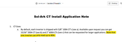
The manual specifies that you have to use CTs when you have multiple inverters. The more inverters you have, the more likely you are to go over this limit!! And I also now found in the CT Sensor Integration document, that they say 80A is the max that you can monitor via the CTs!

Also note how it says "one inverter". Now the question is, does that mean only when using the CTs? Or also when you have passthrough..?? It only takes a 200A service feeding an all electric house and a workshop with a welder, large air compressor etc. to quickly hit that 80A! Shoot, even without a workshop, I could see an all electric house sometimes going over 80A. And while in a lot of circumstances it really wouldn't matter if the inverter isn't monitoring accurately when the draw goes over that, it's pretty sad that the inverters are hyped to have 200A passthrough and to be stackable, but they can't actually monitor over 80A of grid draw.
2TrevorJ
Bend the Joules
My setup has recorded 29.7 kW of grid draw at somewhere around 236-243V. It showed no sign of being maxed out or hitting a limiter (there was still slight variance). 124A or so.
While that may not be 200A bit it's also not 111-116A as was speculated.
Just the normal/included 15K sensors run to my master inverter (no CTs on my slave unit).
While that may not be 200A bit it's also not 111-116A as was speculated.
Just the normal/included 15K sensors run to my master inverter (no CTs on my slave unit).
That is very interesting! I wish I would have an easy way to "manufacture" that size draw, but at home I'm off-grid and our shop is as well, so I don't even have an easy grid source to test it out from.My setup has recorded 29.7 kW of grid draw at somewhere around 236-243V. It showed no sign of being maxed out or hitting a limiter (there was still slight variance). 124A or so.
While that may not be 200A bit it's also not 111-116A as was speculated.
Just the normal/included 15K sensors run to my master inverter (no CTs on my slave unit).
Similar threads
- Replies
- 12
- Views
- 311
- Replies
- 4
- Views
- 491
- Replies
- 4
- Views
- 191


