diy solar

diy solar

Adding storage to my Enphase system

For the last few weeks I've been reading and trying to catch up through the 47 pages of this post, lots of reading. I'm preparing to add storage to my existing 4kW IQ7 solar system. Question: I seem to recall you also have about 4kW of panels, is that 16 amp limit spelled out in your NEM agreement? Oh by the way, you are really getting your system dialed in!

I do tend to ramble on a bit, but there is a lot of info in my thread, from me an several others who have chimed in. I have thought about starting a new thread about how the storage works, but I am undecided if just keeping t all here is better?

My Enphase solar is 16 x 300 watt Sil Fab panels, for a total of 4,800 DC watts. But each panel is on a basic Enphase iQ7 60 inverter, which tops out at 240 watts, or 1 amp into the 240 volt panel. That 16 panels then can top out at 16 amps, which just happens to be the NEC code 80% constant rating for a 20 amp breaker. My main panel is only a 100 amp panel, with a 100 amp main breaker, so the 120% rule allowed, a 20 amp back feed breaker. Amazing how that all worked out. So my NEM 2.0 agreement with So Cal Edison, and the approved plans with the City of Santa Clarita both state "System equipped with a 20 amp back feed breaker, not to exceed 16 amps of continuous current". And the So Cal Edison agreement also adds "Maximum monthly energy export not to exceed 900 KWHs total". On the best days, my system can just top over 30 KWHs, so 30 days x 30 KWHs = 900 KWHs in a month. Basically, they set that limit if my house didn't use any power and it all exported.

My absolute minimum base load I ever see in my house is over 600 watts. So I could certainly add 600 watts of solar, and I would still never hit the 16 amp export limit. But I want to add 2,000 watts. In the hot summer, this should never be a problem. I have not been able to top up my battery for over a week. The air conditioner is just using too much power. Not only does it deplete the battery each night, some nights before 9 pm even, it uses a lot of power when the sun is shining, and that is taking power that could be charging the batteries. As it is, I only have it drop the charge rate to 5% (7 amps) so the battery is still charging a little, but I have to buy some grid power when that happens. Yesterday, during the 2pm to 3pm hour, With the sun just past solar noon, the battery was charging at 7 amps (at 53 volts = about 400 watts), The air conditioner was running at high output, pulling 14 amps x 240 volts = 3,360 watts, The blower in the furnace pulls another 7 amps at 120 volts = 840 watts. The rest of the house loads looks to have been around 850 watts. The solar was cranking out 3,400 watts AC into my backup loads panel.

So I get loads totaling 400 + 3,360 + 840 + 850 = 5,450 watts - 3,400 watts = 2,050 watts I was buying from So Cal Edison. The A/C did run the entire hour, so I bought just over 1.8 KWH for that one full hour. Without the solar panels or battery, I would have had to buy about 5,000 watts or 5 KWHs. So my existing solar can handle 60% of my load at that time. Adding the extra 2,000 watts of solar, should almost zero it out. And I will still not be exporting any power. When the A/C cycles off, it will just charge the batteries faster.

The only problem is when I have great solar production days when it is cool and I don't have the A/C running for over 4 hours. If the solar panels produce enough to top out the batteries before 4 pm, the solar export could exceed my 16 amp limit caused by the 20 amp back feed breaker limit.

Ideally, I should downgrade the main breaker to an 80 amp, and then I could run a 40 amp back feed breaker. But I would also then have to have the system permitted and inspected again. Not the end of the world, but I also don't wan them to change the terms of my NEM deal either. SO my thoughts are to have a way for my PLC to just turn off a few of the new panels if my export current starts going too high. Another option is turning on dump loads, like electric water heater elements, or commanding the A/C to start. I might even be able to have it fire up my air compressor and top up the tank on the extra solar power. Another option is having the new added panels be DC coupled to charge the battery bank. Once it is full, they just will hold the voltage steady and reduce their power output, but this is wasting some power that I could be exporting 95% of the time. Even with 2,000 watts of additional panels, it will be rare to see my system able to export the full 16 amps. Let's try a little math experiment.

Back in May, I had my best production days, with cool air. On May 11, 2022 the battery bank was completely topped out before 1 pm. The solar panels maxed out the 240 watt inverters from 11:30 am to 3:15 pm pushing about 3,900 watts the whole time. So Cal Edison shows my house was exporting 2,990 watts for the 2pm to 3pm hour. So the house was using my expected 910 watts or so. So If... I had 6,800 watts of panels, instead of my current 4,800 watts, and assumed the production could hit the same target, what does that look like? I can export 16 amps x 240 volts = 3,840 watts. And I need another 900 to run the house = 4,740 watts. 4,740 / 6,800 = 70% of the solar panel production. On this great production day, when did my panels make more than 70% of rated power? 4,800 x 0.70 = 3,360 watts. Looking at the plot, my system made over 3,300 watts from 10:30 am to 4:00 pm. So if my battery is not charging, between those times, I may have to turn off some panels. If I go with 5 x 400 watt panels, I can leave 2 on all the time. But the other 3 may have to turn off once the battery is full, if I don't have enough load on in the house. That is doable. I want to do the disconnect on the DC side, so the Enphase data still sees the panel as there, but not producing. Then the data log will show how much production I am curtailing off. I think I would do it with 2 relays. One will turn off just one panel, and the other turns off two panels. Then my PLC can decide if I need to drop 400, 800, or 1,200 watts of panels. The scan rate on the PLC now could see the current go too high and make the choice in under 10 seconds every time. I could make it even faster if need be. And I can make it predict a little early to be on the safe side. The other benefit os switching the DC side into the Enphase inverter is that there will not be the 5 minute delay. It will just think a bad cloud went over.
 
I do tend to ramble on a bit, but there is a lot of info in my thread, from me an several others who have chimed in. I have thought about starting a new thread about how the storage works, but I am undecided if just keeping t all here is better?
One of the best, if not the best, resource I've read on adding storage to an Enphase system with Schneider. Invaluable!

Okay, so your agreement has the 16 amps continuous spelled out, plus a maximum monthly. Interesting to know that's there in your agreement. So far all I can find in what I think is the NEM agreement from SDG&E is:
1656546421501.png

where they spell out specifics about my particular system, but no instantaneous current or monthly production numbers, the rest of the agreement is seemingly boiler plate.

BTW, I started a thread with a question about the IQ7 Grid Profile setting when adding storage. You likely have knowledge you could add there.
 
Last edited:
I would need to look it over again to find the exact wording, but I think the 16 amp limit may have only in reference to the 20 amp back feed breaker. The NEM agreement certainly did spell out the 900 KWH monthly export limit though.
 
How often does utility read the meter? Are they only aware of the 900 kWh monthly? Or do they read every 15 minutes?

The only technical issue I can find with exceeding 120% rule (actually, with exceeding 100%), assuming backfed breaker is at far end of busbar away from main breaker, is that higher current can run in neutral. Main breaker protects L1 and L2 to 100A, but depending on loads you could get higher current on neutral. 120A at 120% rule, 140A if you put in a 40A backfeed breaker (and backfed 40A, and put 140A loads all on one phase.)
 
I am not sure how often the meter sends data back to So Cal Edison, but I can look at their data and see it has the total consumption for every hour. Obviously, if that exceeded 16 amps of back feed for the whole hour, it would show up. I have never even come close to the 900 KWH in a month. Even before I had the battery, my best day of production with almost now load in the house exported only about 15 KWHs, as my house uses 600 watts x 24 hours = 14.4 KWHs on base load with my refrigerator, computers, network gear, and my Dish Network Hopper system. I would almost need to double my solar production to hit the 900 KWH limit. It is just the 16 amps I am concerned about hitting. The power meter on my house updates a lot faster. As it rotates through it's 6 screens, it only stays on each one for about 10 seconds. And in that 10 seconds, I can see the live watts display change a few times. I would estimate that it is updating the reading on the display about every 2 seconds. It would be very easy for it to store a maximum import and maximum export and send that data back to SCE.

The panel under my meter, where the feed comes in from SCE, is not locked. It only has a screw holding the cover closed. I have taken a look in there, an was going to put my grid side CTs in there. The wires coming up out of the ground are most likely aluminum. The L1 and L2 cables look to be about 2/0 while the neutral wire is smaller, maybe just 1/0 gauge. The insulation is vey thick, but it is an old rubber type, but the modern THHN stuff. That cable is probably original from when the house was built in 1969. I am doing my best to balance my loads across L1 and L2. My worst case imbalance has probably never exceeded 50 amps. And most of the time, I now have it down under 15 amps of imbalance. I have now had my inverter cranking out up to 5,800 watts, a new record for me. Battery current hit 106 amps (I still think it reads a tick low) at 53.2 volts = 5,639 watts. but 3,400 watts of that was the 14 amps of 240 volts going to my central A/C compressor. So that leaves 2,500 watts or so of other loads, and I have them split across L1 and L2 as well. But that thinner neutral wire does have me thinking about it. I will bet it is not fused in any way. I just checked an NEC ampacity chart, and I think my wire size estimates are correct. Aluminum 60C rated 2/0 cables is rated to 115 amps, and the 1/0 is 100 amps. If the cables were copper, the current ratings would be 25% higher.

The scariest part is the tiny bus bar from the Neutral feed wire to the neutral bar along side the breakers. The L1 and L2 bars going up into the meter socket and much larger. That neutral bus bar does look like it's made of copper but with a nickel or tin plating on it where the silverish color block has the aluminum cable is connected, but the bar is under 1/10 inch thick (< 2 mm ?), and maybe 0.3 inch wide (8 mm ?). It seems to me that short 2 inch bar would burn long before the 1/0 aluminum neutral feeder wire. The ground bond to my pair of ground rods on connected to the ground bar side in the breaker panel, so if that bus bar did fail, my neutral lines in the house should still be at ground potential. But the 240 volt transformer output would no long have it's center tap grounded at my house. But it probably would still be grounded by a few neighbors ground bonds. How many homes are shared on each utility transformer? The 12,000 volt feeder is stepped down to the 120/240 just 2 houses away from me. There is a transformer like that on each block. My guess is that it is feeding 8 to 12 houses. But does it have more than one 120/240 output winding?
 
The only technical issue I can find with exceeding 120% rule (actually, with exceeding 100%), assuming backfed breaker is at far end of busbar away from main breaker, is that higher current can run in neutral.
Thai an interesting thought. I have always heard it described as a bus bar capacity issue.
 
Thai an interesting thought. I have always heard it described as a bus bar capacity issue.

It took me a while to figure out. I don't think the NEC guys know about it.

I did read that they realized a "200%" rule would work so long as backfeed breaker was at far end, because no point of busbar carries more than 100%. Concern was if breaker relocated adjacent to main breaker in the future the ampacity would be exceeded, and 120% was a concession to make PV addition possible.

As we all know, centertap of an (isolation) transformer carries current equal to difference between L1 and L2.
But centertap of an auto-transformer carries L1 plus L2. Not obvious at first, but consider watts, amps, Kirchoff's current law and it has to be that way.

If GXMnow was to install a 100A PV breaker and backfeed 100A x 240V = 24,000W of PV, with 24,000W of 120V loads on one leg (200A), PV provides 100A on L1 which goes into load, PV provides 100A on L2 which flows to utility transformer (serving as an auto-transformer). Utility transformer supplies an additional 100A on L1 (magnetically coupled, opposite direction from current in L2.) Neutral from utility transformer supplies 200A on Neutral. Zero power or current comes from utility grid and primary side of utility transformer (it just provides voltage to enable GT PV.)

The neutral wire from utility has to carry 200A, and GXMnow's panel neutral busbar has to carry 200A.

Even without individual customers doing 200%, if everybody did 120%, a utility transformer fused on the primary, backfed from some customers and loaded on a single phase by other customers could overload the neutral wire. (Even 240V loads could overload the low-voltage transmission lines if everybody close to transform had PV and everybody far ran their air conditioner. That doesn't require transformer magic; problem is just that PV customers aren't relocated to far end of transmission line.)

The wires coming up out of the ground are most likely aluminum. The L1 and L2 cables look to be about 2/0 while the neutral wire is smaller, maybe just 1/0 gauge.

The scariest part is the tiny bus bar from the Neutral feed wire to the neutral bar along side the breakers. The L1 and L2 bars going up into the meter socket and much larger. That neutral bus bar does look like it's made of copper but with a nickel or tin plating on it where the silverish color block has the aluminum cable is connected, but the bar is under 1/10 inch thick (< 2 mm ?), and maybe 0.3 inch wide (8 mm ?). It seems to me that short 2 inch bar would burn long before the 1/0 aluminum neutral feeder wire.

Probably neutral busbar is tin-plated aluminum.

If you have two neutral busbars, or if utility feeds center of a single neutral busbar, you can try to split loads across them. Maybe that would mean single-phase loads on L1 should have their neutral wires allocated 50% to left half of neutral, 50% to right half. Same for L2. That way, if loads on L1 and L2 are matched, neutral current doesn't even have to flow through entire busbar. Given half of breakers on left side of panel L1 and half L2, same on right side, this likely happens. Order of neutral wires could alternate.

If all loads on L1, the neutral current could be 50% on half of neutral busbar, 50% on other half.

Breaker panel and utility wires are probably sized assuming no one would really draw 100% of rated current and put it through neutral; big loads like range and furnace are 240V. Breaker panel, wonder what temperature the molded insulation is good for? The busbar is in free air, is short so heat can flow lengthwise, all wires connected to it serve as heatsink.


You can probably find a way to backfeed higher peak watts without exceeding monthly export limit. With a larger inverter and current transformer it would be possible to clip backfeed at 16A, but even exceeding that while remaining under 900 kWh/month probably won't offend the utility.

900 kWh/month is 16A x 240V for 7.8 hours, about a summer day's insolation, correct?
So based on monthly consumption you could size an expanded system to avoid exceeding it. But you have to avoid overloading neutral (busbar and utility wire.)
 
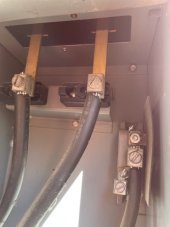
Here is a picture of my breaker panel input terminals before the electric meter. The meter socket is above, and then breakers for the house are to the right.
IMG_1547.jpg
The bus bars look copper, only the end seems tinned where the tin plated aluminum cable connectors are bolted on. The neutral bar goes to the right, through the wall into the breaker panel area. It is actually just 1 inch long with the vertical neutral/ground terminal bar right on the other side of that metal wall. It looks a little corroded in this picture, but it really is just dirty. I think there was a grease of some sort on the terminal connection, and the dirt just stuck to it.

The bus bars for the breakers have the contacts sticking out for breakers on both sides, but the panel is narrow and only allows breakers to the left of the bus bars. So it is just one vertical column, and most of the spaces are half width THQP type breakers. The 100 amp main, 40 amp A/C, and the 20 amp solar back feed are actually the only full width breakers. I just took a measure with my clamp meter. This is interesting because my clamp on amp meter has no way of knowing if the current is flowing in or out.

This is what I got... 4.3 amps on L1, 3.5 amps on L2, and 6.2 amp on the Neutral. The SCE power meter shows I am exporting about 90 watts. The sun is rising, so the numbers are changing fairly quick. The 4.3 amps side is exporting, and the 3.5 is coming back in. The gives a difference of 0.8 amps. At 240 volts, that would be 192 watts, but I'll bet there is some power factor going on, and there was time between the reading, so there could be fluctuation I didn't catch. All in all, at this low of a current, I think the numbers are pretty close. But the most interesting thing to note is that the thinner neutral wire is in fact carrying nearly the full sum of the currents on the L1 and L2 which are in opposite directions. As more loads turn on, it will balance better. The refrigerator and my PC's are both on the L2 side, and that is most of the power draw right now.

Looking at the XW-Pro power readings, it is a bit telling as well. The AC in side is showing 3.9 amps on L1 and -4.3 amps on L2. And the AC Load side shows -6.5 amps on L1 and 1.7 amps on L2. My main panel power meters show loads loads out of the main panel at 16.1 watts on L1 and just 5 watts on L2. The solar output is climbing even more, so there will be some offset from those numbers. I now have 2.01 KW coming in from solar. That is being pushed in on the load side of the XW. That is the -7.8 amps the XW is now showing on L1 output. The L2 output is still showing +, but only 0.2 amps. Most of my house loads are also on these lines, and subtract from the solar coming in. So if we take 7.7 amps at 240 volts, the XW is only seeing 1,848 watts coming in right now, while Enphase is reporting 2.06 KW being produced. That looks like just 215 watts or so being used in my backup loads panel, but I think it is higher, again, some time between readings, and I think a bit of power factor from amp readings to wattage readings. I can't just multiply by 240 volts.

The charge current is ramping up nicely. Out of the 2.13 KW from solar, 1,100 watts are charging the battery bank right now. So the house appears to be using about 900 watts, and I am exporting 100 watts to the grid. My worst imbalance happens while I am at this light load. 6 amps on the neutral is obviously no problem at all, but it is telling that it is far more than either hot leg is taking. I have also found I need to export about 30 extra watts to make the SCE power meter show zero consumption. I wonder if that number varies with the amount of neutral imbalance current? Since the meter has no actual neutral connection, I don't think it can measure it, but what if they do find a way, and charge us for import on each leg separately? That would truly stink.
 
I wonder if that number varies with the amount of neutral imbalance current? Since the meter has no actual neutral connection, I don't think it can measure it, but what if they do find a way, and charge us for import on each leg separately? That would truly stink.

Likely the L1 and L2 leads passing through meter are magnetically summed in a single coil. Vector sum, so watts in and watts out is done correctly. Meter may just compute cross product of current times voltage waveforms, which would happened in analog for a mechanical meter.

It could measure currents and voltages for each leg separately (with wire sensing voltage of neutral.) It doesn't need neutral current to correctly determine power.

I don't think it is capable of simultaneously crediting you $0.05/kWh for exported power on L1 and charging $0.20/kWh for imported power on L2. At any instant they will be summed. NEM 3.0 may tabulate import/export on a second by second basis, or maybe a 15 minute basis.
 
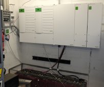
I added a second Schneider MPPT 100-600 charge controller.
The existing single Schneider MPPT 100A-600V maximum output during peak insolation times was 5300 watts,
providing 100A into the XW Pro inverters.

There are almost 9kw of PV currently installed, and I wanted to see how much more power was available for the peak load, which can be 7-8kw.
I was really looking forward to the stats showing how much more power was available from the PV!

Then Mr. Murphy decided to make it overcast here for the next 2 weeks or so......hurricane season.......PIA

There is room on the shed roof to add more rows of PV panels (Winter 22-23 project).
Hope to improve the load support next Summer.

The current conundrum is that the panels I bought are no longer available, so now I have to learn about mixing PV panels.
Am leaving room for a third SCC this time, because these Schneider boxes are multiplying like LEGOs.....

double_charge_controllers copy.jpg
 
Wow, that's quite the wall of Schneider equipment there!

What's the wire pass through in the bottom of the charge controllers look like? Do you have any pics to share?
 
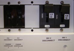
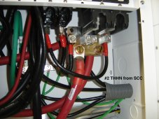
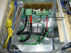
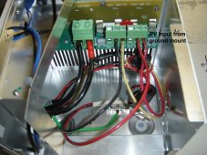
Here is the way I have it wired.
Not obvious from the photos, but the PV cables enter the rear of the SCC from the outside wall, conduit through the concrete block wall.
PDU_DC_breakers.jpgPDU-scc_cables.jpg
DSC01010.JPGDSC01011.JPG
 
pvdude

Are you using anything for rapid shut down and/or arc fault protection?
I know it is not required on a ground mount, and the "shed" is not a living space, so it may not be required. Since my garage is part of my house, evn on the garage roof, I would need under the current code.
 
Gary,
Nope, not required for unoccupied structures here.
I have tried to make things as simple as possible!
 

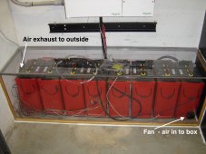
FLA batteries under the inverters?
I suggest an enclosure vented outside. Maybe at least corrugated plastic with foam gaskets, and small fan to maintain negative pressure.
FLA batteries can give off acid mist. Maybe very little when everything is working right, but with imbalance between cells, the high sells outgas while low cells keep taking current.
 
(I think we discussed that before)

Your glass is too clean! I couldn't see it!
I see the pictures are a bit different, a work in progress like all of our systems.
 
Back
Top