diy solar

diy solar

Questions setting up a new Grid-tie system (failures/redundancy/compatibility).

It is because the internal transfer relays are rated to 60 amps per inverter. In theory you could just stack multiple in parallel adding 60 amps of pass through for each inverter (180amps for 3 parallel inverters)

In reality, there is no way to control how much current goes through each relay. You could have 120 amps through one and 30 through each of the other two (when stacking 3)

Also, if the relays need to open, there is not way to ensure each mechanical relay opens at exactly the same instant. In that cause you could put the full 180 amps through one relay.

This isn't unique to Schneider, it's just how electrical works. Outback should have the same requirements.
I figured if they were stacked then the software that keeps them all in sync would determine which one had what load in realtime. Working in IT all these years I'd call it load balancing. So, in the example you had a 160 amp demand it might load two all the way up at @120 and then put the remaining 40 on the third unit. Or divide 160/3 and put 53.3 on each. If not possible you think they'd put that into the software so you can use the gateway to program the inverters for this. It has internal relays so it should be possible to shave incoming loads. So what is the contactor..seems like the pdf I found said it was just a ATS switch? I'm not clear how that switch fixes this issue. Is there a specific link for what this is for the xw switch? From just some quick research it seems like it's just relays and I'd suppose controlled by the aux port on the conext? Wonder how solark does this cause it can do this per engineer 775 videos.
 
I figured if they were stacked then the software that keeps them all in sync would determine which one had what load in realtime. Working in IT all these years I'd call it load balancing. So, in the example you had a 160 amp demand it might load two all the way up at @120 and then put the remaining 40 on the third unit. Or divide 160/3 and put 53.3 on each. If not possible you think they'd put that into the software so you can use the gateway to program the inverters for this. It has internal relays so it should be possible to shave incoming loads. So what is the contactor..seems like the pdf I found said it was just a ATS switch? I'm not clear how that switch fixes this issue. Is there a specific link for what this is for the xw switch? From just some quick research it seems like it's just relays and I'd suppose controlled by the aux port on the conext? Wonder how solark does this cause it can do this per engineer 775 videos.
Load balancing in the IT world, you can move the traffic around on command.

With AC current it's going to go wherever the resistance is lowest. There is no way to steer it. If your inverter #2 and #3 have more wire length, the resistance will be higher and current lower.
You can't activately transfer current flowing through 3 parallel relays.

This is assuming you are talking about passthrough current (from the grid)
If you are talking about the Schneider supporting loads with stacked inverters, then it works as you'd expect. The world to split the load evenly assuming some programming of settings is correct.
But the relays are for passthrough, not inverter output, so I doubt that was your question.

I don't know what Sol-Ark has going on or which unit you are referring to. I hear the new one has 200 amp passthrough.
Yes the new one has 200 amp pass-through but I thought he said it could balance loads when they were stacked. I understand what you're saying about load balancing tcp vs electricity ..I wasn't trying to compare the fundamentals just the context. Wonder if it would be possible for a internal circuit on each inverter to increase / decrease resistance in real time and then monitor each inverter as it adjust these values to get the flow even? Wonder if that's what that external switch does? I wanted to plan for three inverters so this was interesting to learn.


Are you saying there's a software setting in the gateway to cap a passthrough per inverter?

"In theory you could just stack multiple in parallel adding 60 amps of pass through for each inverter (180amps for 3 parallel inverters)"
 
Last edited:
Yes the new one has 200 amp pass-through but I thought he said it could balance loads when they were stacked. I understand what you're saying about load balancing tcp vs electricity ..I wasn't trying to compare the fundamentals just the context. Wonder if it would be possible for a internal circuit on each inverter to increase / decrease resistance in real time and then monitor each inverter as it adjust these values to get the flow even?
I've never heard of anyone offering this "feature"

Resistance= heat and wasted energy.

Also, the adjustment would be very small and precise. I'm not sure it's possible to build with off the shelf components.
Wonder if that's what that external switch does?
The external contactor allows current to flow around the inverter so the internal transfer relays can't be overloaded.
I wanted to plan for three inverters so this was interesting to learn.


Are you saying there's a software setting in the gateway to cap a passthrough per inverter?
No, not really. I believe it will open the relay at 60 amps, but I haven't tested this or gone looking for the setting.
"In theory you could just stack multiple in parallel adding 60 amps of pass through for each inverter (180amps for 3 parallel inverters)"
 
I've never heard of anyone offering this "feature"

Resistance= heat and wasted energy.

Also, the adjustment would be very small and precise. I'm not sure it's possible to build with off the shelf components.

The external contactor allows current to flow around the inverter so the internal transfer relays can't be overloaded.

No, not really. I believe it will open the relay at 60 amps, but I haven't tested this or gone looking for the setting.
"The external contactor allows current to flow around the inverter so the internal transfer relays can't be overloaded."

Gotcha... And, you're right about the heat from resistance. I think there's other ways to clamp down. Midnight was talking about it in there rosie inverter but to what point I don't remember. Thanks friend for the input..have a nice evening sir.
 
Wonder if it would be possible for a internal circuit on each inverter to increase / decrease resistance in real time and then monitor each inverter as it adjust these values to get the flow even?

Linear regulator - drops voltage across it and burns power, inserting "real" resistance".

If you fed the two lines through two windings of a transformer, e.g. two 120VAC 50A windings, that would act as a choke and only let current through one if also going through the other. "imaginary" reactance, coupled. Unless both relays close, near zero current would flow, voltage at load collapses unless inverter keeps supplying.

My Sunny Island is stacked 2s2p, showed 3:1 imbalance at first with about 60' of 6 awg (matched length) and one pole each of QO270 breaker. Replaced that with Schneider 2 pole multi-9 63A, and matched about 9:10.

I think the deal with the Schneider is timing of switching. At least with SMA, inverter can source/sink from battery while bypassing, which could keep current within limit during brief delay before parallel relay switches.
I remember this being part of their new system. Maybe a faster semiconductor is key?

 
Switchers take care of regulating flow of power, converting voltage & current.
SiC apparently has lower losses (and faster parasitic diode.)

But when connecting battery to capacitor bank, through a wired connection not a switching supply, there would be a surge which is a problem.
So long as the load doesn't turn on before precharge is complete, it can be precharged through resistive element or switching element (with inductor). You don't want to just suddenly close a zero ohm switch because something will get over-stressed. The capacitors if nothing else.

All that is needed to let a precharge circuit do its job is delay in load turning on (or communication e.g. "power good" to enable it.)
Thanks for this explanation!
 
Question, have you guys seen the Rosie videos of it surging to like 27k with compressors and other heavy loads? It started a bunch of dewalt compressors along with lights. It didn't start this other compressor but it seems like it almost got there. The guy says even his dual stacked conext 6848 can't start it and they have a transformer where rosie does not. It would be a game changer to one day have a light weight and highly efficient inverter start heavy loads.


"The external contactor allows current to flow around the inverter so the internal transfer relays can't be overloaded."
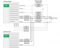
This is the Schneider external contactor circuit & equipment, required when exceeding the 60A internal relay limit.
I have purchased the relay and contactor, but will not install until there is good reason - my system is nowhere near the 60A limit (14.4kVA).
Circuit looks like a wad'o crap that the engineers drew up on a paper napkin, while at lunch.

From this publication:
XW Pro Multi-unit Design Guide
990-91373A April 2021
Schneider_external_relay_contactor copy.png
 
This is the Schneider external contactor circuit & equipment, required when exceeding the 60A internal relay limit.
I have purchased the relay and contactor, but will not install until there is good reason - my system is nowhere near the 60A limit (14.4kVA).
If you're not going to pass through more than 60 amps (from generator or grid) there's no reason to add the external contactor.

Circuit looks like a wad'o crap that the engineers drew up on a paper napkin, while at lunch.
Here's hoping it was at least a good lunch! Lol
 
"Circuit looks like a wad'o crap that the engineers drew up on a paper napkin, while at lunch." lol

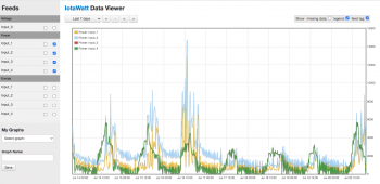
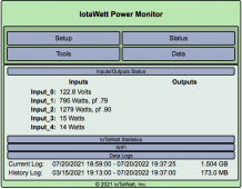
From what I was reading last night you only need this when using more amps than two units can provide with their 60amp onboard relays? So, if I have two 6848's I should be able to pull 120A without having to do anything like this? If that's the case I was rethinking this and it's really not a huge deal for me as I really don't see myself going that high. And, if I still want three stacked but don't plan on going over 120A I still don't need it. I really need to do a power audit. I was looking for some affordable options to clamp something to my mains so I can get a idea of my watt/amp usage. Something maybe like this:

 
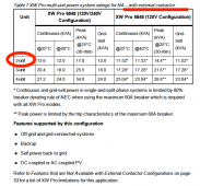
Looks like two XW Pro 6848's peak @ about 71A - if the external contactor is used.
Three peak @ 106A.
Screen Shot 2022-07-20 at 19.42.00.png
 

diy solar

diy solar
Back
Top