I bought JK-B2A24S20P and want to use it with 16 battery cells (3.2V 280Ah each ). When all cells are connected together,I have more than 50V .
Before connecting battery with MPPT tracker I would like to test that BMS with the battery cells . Is it possible?
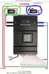
I connected cables marked B- to main battery minus and cable P- to battery main plus. Is it correct?
Thank you for help
Before connecting battery with MPPT tracker I would like to test that BMS with the battery cells . Is it possible?
I connected cables marked B- to main battery minus and cable P- to battery main plus. Is it correct?
Thank you for help