diy solar

diy solar

Ground fault from PV conductors Positive or Negative

ig1628

New Member
Joined
Jul 16, 2021
Messages
51
Hello Forum, I have a very odd issue. With a multimeter with one lead on positive or negative the other lead on ground(earth) I show voltage. The voltage varies depending on solar irradiance (in excess of 160v +).
I have also used a oscilloscope to see the wave form and it has a very odd wave form. This happens at the PV Array as well as the inverters inputs (pictures attached). If I disconnect (via breaker and or pv disconnect)the PV array I don't get the voltage to ground (earth). Not sure if this is a normal occurrence with PV systems but, I do know ground conductors are not supposed to have potential on it. I will add that very little current (mA) if any.
Some input would be greatly appreciated.
@Will Prowse

20220928_181258.jpg20221011_173831.jpg20221108_183228.jpg
 
Last edited:
How long has your system been operational? Does it do this all the time or more so when wet out? Wondering if you have a short in your PV wiring.
 
It's been operational since October 2021, that's what I thought but when I disconnect the pv arrays from the inverters the voltage goes away, I have been trying to figure this out for several months done all king of troubleshooting. This weekend I am going to start from scratch in the troubleshooting. I have two 16 panel arrays and I am pretty sure I isolated one set from the other set individually when I was testing but I will reconfirm.
Thank you so much for your reply I will definitely keep you in the loop.
 
Last edited:
When you disconnect the PV wiring from the inverters you aren’t able to measure VDC from red and black wiring? If so, trace back to your fuses, then disconnect from array with loads removed and test for high impedance across each leg back to each array series path.
 
When you disconnect the PV wiring from the inverters you aren’t able to measure VDC from red and black wiring? If so, trace back to your fuses, then disconnect from array with loads removed and test for high impedance across each leg back to each array series path.
I have checked at the breaker(have not actually pulled conductors from the inverters) as you seen in the picture showing 194+ voltage at the top of the breaker where it goes to the inverters as well as the bottom coming from the pv arrays, however I don't get that high voltage it's about 4 to 9 volts dc with the breaker off and lead on ground(earth) and the other on positive. I did notice when I check the negative to earth the voltage is higher than positive, which I guess could mean one of the panels negative might be shorted to the frame(earth) or in the panel could be shorted.
I get what you are saying and I have not check ohms across the pos and neg conductors. I will definitely do so this weekend.
Thanks again.
 
I believe it's normal for there to be voltage potential between the DC conductors and earth ground specifically because most PV systems are isolated, there is no path to ground on either conductor to dissipate the potential.
You stated there is little or no current. A ground fault is defined as "current taking an unplanned path back to source". With no current its not a ground fault.
In the original post the term "power" to ground was used. Power in Watts = Volts x Amps. Without amps there is no power its just voltage potential.
I'm not saying your system is normal or safe, only pointing out its possible there has been a misinterpretation of the readings you are seeing. In any case continue to use caution when working with HV DC.

Here is a link to an article that discusses "system" vs. "equipment" grounds.
 
When you disconnect the PV wiring from the inverters you aren’t able to measure VDC from red and black wiring? If so, trace back to your fuses, then disconnect from array with loads removed and test for high impedance across each leg back to each array series path.


I believe it's normal for there to be voltage potential between the DC conductors and earth ground specifically because most PV systems are isolated, there is no path to ground on either conductor to dissipate the potential.


You stated there is little or no current. A ground fault is defined as "current taking an unplanned path back to source". With no current its not a ground fault.


In the original post the term "power" to ground was used. Power in Watts = Volts x Amps. Without amps there is no power its just voltage potential.


I'm not saying your system is normal or safe, only pointing out its possible there has been a misinterpretation of the readings you are seeing. In any case continue to use caution when working with HV DC.


Here is a link to an article that discusses "system" vs. "equipment" grounds.


Hello and thank you for your reply, yes poor choice of words on my part.


I believe it's normal for there to be voltage potential between the DC conductors and earth ground specifically because most PV systems are isolated, there is no path to ground on either conductor to dissipate the potential.
You stated there is little or no current. A ground fault is defined as "current taking an unplanned path back to source". With no current its not a ground fault.
In the original post the term "power" to ground was used. Power in Watts = Volts x Amps. Without amps there is no power its just voltage potential.
I'm not saying your system is normal or safe, only pointing out its possible there has been a misinterpretation of the readings you are seeing. In any case continue to use caution when working with HV DC.

Here is a link to an article that discusses "system" vs. "equipment" grounds.
Hello and thank you for the reply,. Poor choice of words, correct not power, ground fault, just voltage reading on conductors to earth. I will elaborate as to how I came about testing on my dilemma. In the summer of this year I was washing off the panels with the water hose in hand and I felt what seemed to be a tingling while my hands where wet and holding the hose and touched the panel frame. Wasn't bad I am used to dealing with potential in my line of work in both control voltage and line voltage in industrial maintenance as a Automation Technician. So that being said I grabbed my meter and started testing on my combiner box and now this is where I am at. I was hoping that the voltage to earth was normal on PV conductors but there is that tingling I felt. Like mentioned before I didn't get a reading with my amp clamp, however I have not pulled the cables and tested inline with the conductor. Hopefully it won't be raining this weekend so can can do some more troubleshooting. I was hoping that maybe someone on this forum might have tested to earth at some point I don't know anyone at the moment the has solar set up. Btw Thank you for the link.
 
Another question should I have surge protector (lightning arrestor) at the inverter side? Presently I have them on the arrays and on the equipment side. I also had a 4 gauge bare wire running from the pv to the equipment in ground, I disconnect it when I found this voltage to ground i have read different opinions on this, ever Mike Holtz said it was crazy to have the panels to ground rod because of the potential of nearby lightning and might attract it to the panels.
 
Last edited:
Another question should I have surge protector (lightning arrestor) at the inverter side? Presently I have them on the arrays and on the equipment side. I also had a 4 gauge bare wire running from the pv to the equipment in ground, I disconnect it when I found this voltage to ground i have read different opinions on this, ever Mike Holtz said it was crazy to have the panels to ground rod because of the potential of nearby lightning and might attract it to the panels.
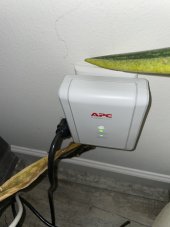
I live in FL so like to have shunts at every input interface including AC grid input, PV to Inverter input, and Ethernet connections. I also plug my sensitive electronics into APC protectors, see attached. I agree with Mike Holt regarding tying earth ground back to the meter location, however due to being 125’+ I added a supplemental ground rod at my house sub panel to ensure sufficient and timely dissipation while ensuring the potential remains the same.
 

Attachments

  • FC8D855F-0E4E-4097-948B-2614063CE177.jpeg
    FC8D855F-0E4E-4097-948B-2614063CE177.jpeg
    101.3 KB · Views: 4
Hello and thank you for the reply,. Poor choice of words, correct not power, ground fault, just voltage reading on conductors to earth. I will elaborate as to how I came about testing on my dilemma. In the summer of this year I was washing off the panels with the water hose in hand and I felt what seemed to be a tingling while my hands where wet and holding the hose and touched the panel frame. Wasn't bad I am used to dealing with potential in my line of work in both control voltage and line voltage in industrial maintenance as a Automation Technician. So that being said I grabbed my meter and started testing on my combiner box and now this is where I am at. I was hoping that the voltage to earth was normal on PV conductors but there is that tingling I felt. Like mentioned before I didn't get a reading with my amp clamp, however I have not pulled the cables and tested inline with the conductor. Hopefully it won't be raining this weekend so can can do some more troubleshooting. I was hoping that maybe someone on this forum might have tested to earth at some point I don't know anyone at the moment the has solar set up. Btw Thank you for the link.
Definitely want to find that leakage as water intrusion is likely the cause. Use insulated gloves when doing your testing. Consider this article regarding PV testing with snippet below - https://www.solartesalonspa.com/how-to-test-the-photovoltaic-array-before-use/

Electrical performance test of photovoltaic cell modules
Photovoltaic cell modules should generally be tested on the open circuit voltage, open circuit voltage, Short-circuit current, volt-ampere characteristic curve, fill factor and maximum output power are measured, but the following methods can be used for testing if the above conditions are not met.


How to test the photovoltaic array before use?
Electrical performance test of photovoltaic cell module
 
Hello Forum, I have a very odd issue. With a multimeter with one lead on positive or negative the other lead on ground(earth) I show voltage. The voltage varies depending on solar irradiance (in excess of 160v +).

As expected with non-isolated inverters
 
Definitely want to find that leakage as water intrusion is likely the cause. Use insulated gloves when doing your testing.

Electrical performance test of photovoltaic cell modules
Photovoltaic cell modules should generally be tested on the open circuit voltage, open circuit voltage, Short-circuit current, volt-ampere characteristic curve, fill factor and maximum output power are measured, but the following methods can be used for testing if the above conditions are not met.


How to test the photovoltaic array before use?
Electrical performance test of photovoltaic cell modules
 
Definitely want to find that leakage as water intrusion is likely the cause. Use insulated gloves when doing your testing. Consider this article regarding PV testing with snippet below - https://www.solartesalonspa.com/how-to-test-the-photovoltaic-array-before-use/


Electrical performance test of photovoltaic cell modules


Photovoltaic cell modules should generally be tested on the open circuit voltage, open circuit voltage, Short-circuit current, volt-ampere characteristic curve, fill factor and maximum output power are measured, but the following methods can be used for testing if the above conditions are not met.


Electrical performance test of photovoltaic cell module

Definitely want to find that leakage as water intrusion is likely the cause. Use insulated gloves when doing your testing. Consider this article regarding PV testing with snippet below - https://www.solartesalonspa.com/how-to-test-the-photovoltaic-array-before-use/

Electrical performance test of photovoltaic cell modules
Photovoltaic cell modules should generally be tested on the open circuit voltage, open circuit voltage, Short-circuit current, volt-ampere characteristic curve, fill factor and maximum output power are measured, but the following methods can be used for testing if the above conditions are not met.


How to test the photovoltaic array before use?
Electrical performance test of photovoltaic cell module
Yes definitely, all of the testing and troubleshooting I have done has been dry. I only notice this some time in the middle of summer I actually have not tested during rain yet. As for water intrusion I'm not sure if that is or was the root cause, this might have been happening since I installed the system, not sure because I never thought about checking the pv conductors to earth.
 
Yes definitely, all of the testing and troubleshooting I have done has been dry. I only notice this some time in the middle of summer I actually have not tested during rain yet. As for water intrusion I'm not sure if that is or was the root cause, this might have been happening since I installed the system, not sure because I never thought about checking the pv conductors to earth.
There is nothing wrong, ground is bonded to neutral and non isolated inverters with have the PV voltage +/- to ground.
 
There is nothing wrong, ground is bonded to neutral and non isolated inverters with have the PV voltage +/- to ground.
Thank you for the information. Apparently some solar distributors don't know this I was 2 months with tech support, engineers and the manufacturer, to figure out what would be causing it and never actually got an answer. And finally got issued rma for the inverters. The only thing that has a little skeptical it the fact that in the summer I felt electrical tingle wil the was cleaning and spaying the panels with the water hose.
 
Definitely want to find that leakage as water intrusion is likely the cause. Use insulated gloves when doing your testing. Consider this article regarding PV testing with snippet below - https://www.solartesalonspa.com/how-to-test-the-photovoltaic-array-before-use/

Electrical performance test of photovoltaic cell modules
Photovoltaic cell modules should generally be tested on the open circuit voltage, open circuit voltage, Short-circuit current, volt-ampere characteristic curve, fill factor and maximum output power are measured, but the following methods can be used for testing if the above conditions are not met.


How to test the photovoltaic array before use?
Electrical performance test of photovoltaic cell module
Thank you for the info, Solar Guppy mentioned that with non isolated inverters it will cause voltage potential on the conductors for the PV arrays. So I will try and gather more information on this issue. Thanks so much foe tour time.
 

diy solar

diy solar
Back
Top