RTL44
New Member
- Joined
- May 30, 2022
- Messages
- 67
Hi,
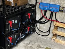
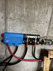
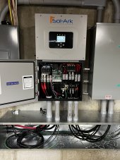
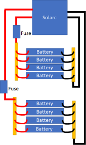
Although I have learned a lot from research and this forum, I am still pretty new to this. I finally was able to purchase 8 - 48V LiFePO4 server rack batteries (5.12 kWh each) to use with my Sol-Ark 15k. The batteries come with 8 inch 2AWG cables per unit.
My questions are:
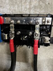
1) Is 2AWG adequate for connecting 8 of these together?
2) Would there be any advantage/disadvantage to putting all 8 in a server rack and then into one of the battery inputs of the Sol-Ark vs. connecting 4 into input 1, and the other 4 into input 2?
3) I assume it would be better to use bus bars in a cabinet vs. parallel/diagonal wiring. If so, what dimensions should my bus bar be to adequately handle the 8 batteries?
Thank you for any help you can provide. I live in Mexico and it is not easy to find equipment or experts in this field.
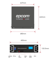
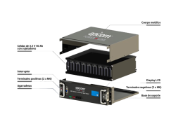
Attached are some pics/specs and a link to the manual of the batteries & the Sol-Ark manual
Although I have learned a lot from research and this forum, I am still pretty new to this. I finally was able to purchase 8 - 48V LiFePO4 server rack batteries (5.12 kWh each) to use with my Sol-Ark 15k. The batteries come with 8 inch 2AWG cables per unit.
My questions are:
1) Is 2AWG adequate for connecting 8 of these together?
2) Would there be any advantage/disadvantage to putting all 8 in a server rack and then into one of the battery inputs of the Sol-Ark vs. connecting 4 into input 1, and the other 4 into input 2?
3) I assume it would be better to use bus bars in a cabinet vs. parallel/diagonal wiring. If so, what dimensions should my bus bar be to adequately handle the 8 batteries?
Thank you for any help you can provide. I live in Mexico and it is not easy to find equipment or experts in this field.
Attached are some pics/specs and a link to the manual of the batteries & the Sol-Ark manual


")