diy solar

diy solar

JBD BMS Relais Problem

peregrines

New Member
Joined
Jul 1, 2022
Messages
17
Hi!
I just encountered a problem with my JBD BMS.
I have a 16s Lifepo4 System running with Victron Multiplus.
Everything seemed to run just perfect till today my system reached a low voltage state (of course not too low ;)
I was standing next to my system to check if it would turn off according to my settings.
The JBD turned the relais off with a loud "click" but then, after some seconds turned it back on again.
Then it then kept doing the same thing in an interval of some seconds. On - Off - On - Off - On - ...

I decided to turn off the Multiplus (for security reasons) and now it stopped doing it.
Could anybody give me a hint where the problem is?
I am sure I configured something wrong (using millions of Youtube-Tutorials and this great forum) ... but I dont really now how to go from there.
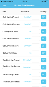
Or could someone post his Xiaoxiang/JDB BMS settings for a 16s Lifepo4 280AH system?

Thank You!
 
The JBD turned the relais off with a loud "click" but then, after some seconds turned it back on again.
Then it then kept doing the same thing in an interval of some seconds. On - Off - On - Off - On - ...
It sounds like your system is behaving as it should but not as you would like.

I suspect that your relay is pulling down the voltage of the battery to where the BMS is set to turn the relay off. After a few seconds, the battery recovers and the BMS turns the BMS back on. I suspect this is also the case with your Multiplus, where it also pulls the battery voltage down and when it is turned off, the battery is able to recover.

If you set your BMSs cutoff voltage and reconnect voltages farther apart, this affect may be minimized. Maybe something like 2.6V and 3.0V?

Can you post a screenshot of your BMS settings?
 
I have same issue but 0.4V difference between cutoff and recover voltage (high and low cutoff) doesn’t change a thing. The relay still goes on-off every second.
Settings are: 3450 and 3050 high and 2550 and 2950 low cutoff and recover.
Does anyone have other ideas how to solve ?

Im discussing already more than 10 days with JBD BMS vendor from AliExpress without any success

Any help ???
I do not trust the system anymore and each time I leave the house I shut down the system completely…
 
Settings are: 3450 and 3050 high
You should set the cutoff at or near the safety limits of the cell. LiFePO4 high limit is 3.65V. I am a little conservative and use 3.64V and 3.62V recover.

3050 recover for high would require the battery to be 90% discharged before the BMS reconnected, makes no sense.

This is an old thread so probably ok to hijack. Can you post pics of your settings?
 
3.65V is in my opinion too high. Ok this is rather a strategy, not necessarily “the truth”. I follow guidelines from Andy from the off-grid-garage in Australia with his YT Chanel. There are a few reasons why these settings and I believe them. Mostly like longevity of the cells. As you stress them less and stil have like 95% of their capacity.
But that is a different topic/discussion…

Besides that, the 300mV difference was suggested by JBD. But from 3700 mV to 3400 mV. This to stop the clicking of the relay. Unfortunately, this didn’t solve the issue. So I pushed it even further to 400mV difference. Even that didn’t solve the clicking.
Then I changed the settings back to my initial values and I posted my questions on the internet… as the manufacturer has no solution, maybe somebody else has an insight that JBD doesn’t want to share with me…

My settings are much closer together. Like 50mV apart.

here a screenshot.
 

Attachments

  • 91DEF007-EC29-43BC-806F-5D4A6C873D2E.png
    91DEF007-EC29-43BC-806F-5D4A6C873D2E.png
    460.3 KB · Views: 15
3.65V is in my opinion too high. Ok this is rather a strategy, not necessarily “the truth”.
Are you using your BMS as a charge controller?
The BMS should be used to prevent damaging your cells, and that point is above 3.65V and should not occur unless something goes wrong with your charging. So battery longevity should not be an issue.

If your battery high voltage cutoff is 3.45Vpc, how high is your charger set to and how long is the absorb stage?

I'm all for conservative charging and have been one of the most conservative here for years but your strategy sound strange.
 
I have 3400Wp on the roof
Victron Mppt charger 250/60
JBD smart bms 200A
16 LFP cells 280Ah
Victron inverter Multiplus II 48/5000/70
and Victron Cerbo GX.
Still connected to the grid. But should be almost independent from it. My consumption is quite low but I needed batteries to power some water pumps in case of grid failure to prevent house being flood at high rainfall. Which happens a few times per year in south of France.
 
Victron kicks in at high & low pack voltages but not at cell level. Therefor the smart BMS who talks to the Victron. Or do I have it set up wrong ?
Victron is programmed with ESS this is Energy Storage System for those who know the system.
 
Actually… the BMS is indeed the charge controller as it overrules the parameters of the Mppt charge controller. That is the function of a Smart BMS: take over the charge protocol from the MPPT.

Unless it is faulty like mine and then the whole systems rely on a faulty part…
Luckily the charging and discharging seems to go fairly correct (I think) besides the clicking of the BMS.

I do get warning about the high ripple on the DC line (due to on and off supply of DC power each time the relay goes on and off) and at night when no sun power is available I get low battery warnings…

The noice of the relay is absolutely annoying and is wrong functioning whatsoever. But I fear the moment the relay breaks down in an open or closed position, which is in no case good for the battery pack. Uncontrollable under or over-voltage is then unavoidable as I see it.

Your thoughts?
 
Actually… the BMS is indeed the charge controller as it overrules the parameters of the Mppt charge controller. That is the function of a Smart BMS: take over the charge protocol from the MPPT.
I understand what you are doing but do not have experience with that.

Lets conjure @sunshine_eggo to see if he can help. Otherwise i'd recommend starting a thread with a title that specifically asks about controlling viltron setup with a smart BMS.

Good luck, wish i knew enough to help.
 
He is using his BMS to control his Victron charging. I am not familiar with how this works.

Can't comment on the JBD specifically as I'm not familiar with the implementation, but the general way is to specify a peak voltage, and the GX would regulate chargers on that basis. Unfortunately, I suspect the BMS will also trigger it's own protection, which would cause secondary issues.
 
What I understand is that the BMS takes over the lead in the charging steps. All parameters like over and under voltage on cell level and on battery pack level are programmed into the BMS. Beside that there are also other safety parameters like shortcut protection and over and under temperature protection.
Al this info is then returned to the Victron system so this can use the info to display on a nice info graph. 6D6496A8-597C-4596-AF65-142A9AC4431E.jpeg
 
I can only be confident in what I know my Batrium does with my Victron system. My Batrium nas NO INDEPENDENT means of protecting a battery. It relies on either controlling the Victron system within BMS set parameters OR an external relay must be installed to completely isolate the battery.

In the case of the JBD, it's programmed parameters result in direct over/under-voltage protection, i.e., it opens the FETs and prevents current from flowing in the desired direction.

The JBD must then also have a secondary level of controls that it uses to manage the GX device WITHOUT triggering its own protections.

What driver are you using to interface the JBD with the GX?
 
What I understand is that the BMS takes over the lead in the charging steps. All parameters like over and under voltage on cell level and on battery pack level are programmed into the BMS.
It sounds like the system is working as implemented: The charger charges up to BMS specified 3.45Vpc at which point the BMS turns the battery relay off.

My thought is that with conservative charging to 3.45Vpc, the MP/Cerbo could just be set to charge to (3.45 x 16) = 55.2V assuming that the cells are balanced enough. And use the BMS as a last line of protection at around 3.65Vpc (as how usually implemented).

Is there a downside to this approach?
 
Okay. I think I understand now.

3.65V is in my opinion too high.

You are wrong. BMS should be set to the absolute limits of the cells. The BMS should NEVER be used for routine control of charge or discharge limits. The charging equipment should be configured to operate INSIDE BMS limits. BMS should NEVER trigger unless something goes wrong.

You are not complying with the installation instructions of the @Louisvdw driver.

Ok this is rather a strategy, not necessarily “the truth”. I follow guidelines from Andy from the off-grid-garage in Australia with his YT Chanel. There are a few reasons why these settings and I believe them. Mostly like longevity of the cells. As you stress them less and stil have like 95% of their capacity.
But that is a different topic/discussion…

Besides that, the 300mV difference was suggested by JBD. But from 3700 mV to 3400 mV. This to stop the clicking of the relay. Unfortunately, this didn’t solve the issue. So I pushed it even further to 400mV difference. Even that didn’t solve the clicking.
Then I changed the settings back to my initial values and I posted my questions on the internet… as the manufacturer has no solution, maybe somebody else has an insight that JBD doesn’t want to share with me…

My settings are much closer together. Like 50mV apart.

here a screenshot.


The BMS driver is set for 2.9-3.45V operating range with 50A charge and 60A discharge limits. The BMS safeties MUST be set outside this - the typical 3.65 and 2.5 preferred, and the instructions convey this requirement but recommend 3.65 and 2.85.

Additionally, your battery must be sufficiently top balanced to achieve the 3.45V average without triggering OVP.

The way this works is it sends a 55.2 (3.45*16) battery limit voltage to the GX via DVCC. DVCC can further restrict current and voltage if so desired.

DVCC will direct any attached and operational chargers to charge until 55.2V is reached, and then it is held there.

It sounds like your battery is imbalanced. You will experience issues until you 1) resolve the imbalance and 2) correctly configure your BMS.
 
It sounds like the system is working as implemented: The charger charges up to BMS specified 3.45Vpc at which point the BMS turns the battery relay off.

My thought is that with conservative charging to 3.45Vpc, the MP/Cerbo could just be set to charge to (3.45 x 16) = 55.2V assuming that the cells are balanced enough. And use the BMS as a last line of protection at around 3.65Vpc (as how usually implemented).

Is there a downside to this approach?

I missed your reply when I posted. It is the intended approach of the driver developer.

He's choosing to run an imbalanced battery with BMS settings against the installation instructions, so it's all user error.
 
OK need to check into this futherb after next week. I’m gone the whole week and decided to shut down the system completely.

BUT. I do not understand how the wrong setting inside the dvcc and BMS causes the relay of the BMS klick every second. Which was the initial reason for my concerns. I’m more worried about this relay right now than the correct high voltage settings. Could this also be caused by these settings ?
Once I know what to do about the clicking I can worry about the perfect settings.
The clicking occurs at every stage of the charge curve right from the beginning at 3,2V up to the overvoltage shut down of one of the cells. So could this clicking be caused by wrong settings in the Victron ?
Also, when I disconnected the battery pack with BMS from the Victron the clicking was also happening… strange !

PS. Last my cell OVP was set at 3,6V in the BMS and 57,6 (3,6 x 16) in the dvcc
 
Last edited:
What I understand is that between the low voltages and about 3.8 - 3.9-ish volt there is no way to tell if cells are unbalanced. So why would the BMS start clicking?

Also I was tricked by the voltage at low stages. Now I see I need to top balance better (next week). Beginners fault assuming that all batteries within one delivery batch are charged equally…
 
Last edited:

diy solar

diy solar
Back
Top