diy solar

diy solar

JBD JBD-AP21S001 BMS problem for 16s

Joined
Oct 25, 2023
Messages
8
Location
Italia
Hello everyone from Alvaro, Pisa Leaning Tower Italy.
My home-made off grid system has been working perfectly for 6 months but I don't know if the 16 48V cells are in good health.
5 months ago I bought the JBD BMS but I couldn't make it work, it's probably me that doesn't work :).
In Italy it is difficult to find help for JBD BMS and in these rainy days I am trying again to make it work but I don't know the right parameters for the LiFePo4 280 A, I have installed the xiaoxiang App again, I attach photos of the current situation.
There is no point in taking up too much space describing the whole situation, if anyone wants to help me they can ask everything they need, I can also send videos privately on my YouTube channel.

Bye and have a good day.
 

Attachments

  • IMG_20231027_112139_615.jpg
    IMG_20231027_112139_615.jpg
    895.7 KB · Views: 20
  • AP21S001-16S Wiring Diagram.pdf
    3.5 MB · Views: 22
Have you confirmed the accuracy of those values with a separate voltmeter?

That unit can be used on multiple cell counts. My guess is you have the sensing harness wired incorrectly.
 
Looks like a wiring problem to me too, probe all of the balance leads to make sure you're getting incremental 3.2 volt steps on each pin and confirm that you have gathered all the extra cables and put them on to cell 14 positive as per the instructions. These JBD BMS are actually quite simple to set up as long as you get the wiring correct.
 
Last night I checked the wiring again and in fact I found that the red cable of pin 14 that goes to the positive pole of cell 14 was interrupted and the situation has changed:
Without pin 14
Without pin 14 and with pin 14.
I measured cell 1 with the voltmeter and it has the same voltage as the others. Now I'm going to check pins 0 and 20 again, I also measure cell 1 and the battery pack, take photos and send.
 

Attachments

  • Whithout pin 14.jpg
    Whithout pin 14.jpg
    787.8 KB · Views: 8
  • IMG_20231027_112139_615.jpg
    IMG_20231027_112139_615.jpg
    895.7 KB · Views: 8
The BMS cables B- and C- are NOT connected to the negative pole battery, the ones you see in photo 1 are the inverter and 2 MPPT cables
Cell 1 volts and battery pack volts.
As I said the system has been working well for 6 months but I didn't tell you that you are talking to a 73 year old "apprentice" :D .
Now I'm baking bread (photo 6) but when night comes I check all the pins and if they are connected well
 

Attachments

  • Photo 1.jpg
    Photo 1.jpg
    865.4 KB · Views: 17
  • Photo 2.jpg
    Photo 2.jpg
    854.4 KB · Views: 15
  • Photo 3.jpg
    Photo 3.jpg
    914.8 KB · Views: 15
  • Photo 4.jpg
    Photo 4.jpg
    1 MB · Views: 15
  • Photo 6.jpg
    Photo 6.jpg
    710.5 KB · Views: 17
The BMS cables B- and C- are NOT connected to the negative pole battery, the ones you see in photo 1 are the inverter and 2 MPPT cables
Cell 1 volts and battery pack volts.
As I said the system has been working well for 6 months but I didn't tell you that you are talking to a 73 year old "apprentice" :D .
Now I'm baking bread (photo 6) but when night comes I check all the pins and if they are connected well
Take all those leads going to cell 14 and put them in 1 ring terminal... (old photo from my 8s pack.
Screenshot_20231027-125712.jpg

Edit - welcome to the forum.
 
Take all those leads going to cell 14 and put them in 1 ring terminal... (old photo from my 8s pack.
View attachment 174544

Edit - welcome to the forum.
Thanks, after I checked all the cables and the incremental voltage on all the batteries I try to do what you said, but I don't understand the difference between connecting the 5 cables that go to + 14 with their 5 terminals and connecting them all together on a single terminal
 
Thanks, after I checked all the cables and the incremental voltage on all the batteries I try to do what you said, but I don't understand the difference between connecting the 5 cables that go to + 14 with their 5 terminals and connecting them all together on a single terminal.
I'm not an expert but it's my understanding every connection adds resistance and potential failure points, plus it looks a lot cleaner and I bet it's much easier to tighten down.
I'm also a big fan of drilling and tapping the buss bar to give the balance /sense leads there own connection but I won't be doing that again when I re-assemble my packs.
I'm laughing at myself for saying it looks cleaner as I look at my wiring mess in the attached photos.
 

Attachments

  • IMG_20221024_194454.jpg
    IMG_20221024_194454.jpg
    1.7 MB · Views: 15
  • IMG_20221024_194300.jpg
    IMG_20221024_194300.jpg
    565.5 KB · Views: 15
I'm not an expert but it's my understanding every connection adds resistance and potential failure points, plus it looks a lot cleaner and I bet it's much easier to tighten down.
I'm also a big fan of drilling and tapping the buss bar to give the balance /sense leads there own connection but I won't be doing that again when I re-assemble my packs.

In general, I'm not. By drilling the bus bar, you're reducing the cross sectional area of copper and replacing it with steel.

I'm laughing at myself for saying it looks cleaner as I look at my wiring mess in the attached photos.

both of yours look better than mine. :)
 
Hi everyone, this morning at 5.30 I started to recheck the connections, still following the wiring diagram and they were all perfect, I rechecked the continuity of the small cables pin by pin by disconnecting them from the cells, no problem but in any case I followed your advice and reunited the 6 cables going to the + of cell 14 in a single terminal.
I checked the individual cell volts incrementally and with the two MPPTs off, no problem. to cell 16 51.7 V.
I took many photos but I don't want to take up too much space on the forum, I'll just post a few.
The situation seems to have improved at the 10pm check after 12 hours IMG_20231028_102300_739.jpg but cell 1 is gray at minimum or red at maximum Grafico.jpg but unfortunately I don't know how to understand all the changes on the battery status screen if they are regular, there was a moment while I was making the video when they all became yellow but then cell 1 after a few moments it started to rise again and is now completely red Cella1.jpg , I checked cell 1 with the multimeter and the voltage is the same as all the others 3.28. For the parameters to be set for the BMS I tried to follow a video on YouTube but my English is terrible and I can't read the subtitles translated into Italian by Google, but if I read I can't follow the mouse pointer and the recommended values for the LiFePs , I would have to watch the video frame by frame.
Question, are there photos or a PDF with the standard and safe values to be set via the app?
As you can see in the photo the BMS cables B- and C- are disconnected, IMG_20231028_102007_922.jpgI tried to connect the B- to the negative pole of the battery and then I connected the C- to the inverter cable and to the cables - of the two MPPTs on the bus bar but if I then try to turn on the inverter nothing happens, the inverter does not turn on. so I directly connected the inverter negative to the battery negative together with the 2 MPPT negatives and the system works perfectly.
 
After the night all the cells have this graph Cella 11.jpg

But cell 1 has this graph Cella 1.jpg

Now I try to replace the terminal that goes from pin 21 to the negative pole of the battery pack.
Is there a way to reset this JBD BMS? I wouldn't want to waste entire days and then discover that the BMS is broken, do you have any advice on how to proceed? Thank you. Total V.jpg
 
You can download JBD tools and connect through the PC if you have the interface cable. This would give you more control over the app and allow you to update the firmware if there is a new version available.
 
Thanks, unfortunately at the moment I don't have a notebook available, at home I should have some still working desktop PC to put in the garage, and I have to find the interface to connect it, I hope I can do it but it takes time, bye and good evening.
 
For your information, I paste the chat with the "official" seller to whom I am telling that according to the opinion of several experts this BMS does not work.
Is it normal for you that the chat develops in this way?


[06:50, 7/11/2023] Alvaro Nannicini: "
hi,dear,don't worry,i will help you.
we can try to test it first,is that ok?If there is a wrong,we can refund you or give you the new bms.
can you connect it?And use our new app to analysis it?
How many battery packs do you use?"
[06:50, 7/11/2023] Jane Lee: Don't worry,i will help you.
[06:51, 7/11/2023] Alvaro Nannicini: Okay, tell me what to do
[06:51, 7/11/2023] Jane Lee: You mean you use 280a battery?
[06:52, 7/11/2023] Jane Lee: But the bms is 200a.
[06:52, 7/11/2023] Jane Lee: You can use below 200a battery
[06:59, 7/11/2023] Alvaro Nannicini: Are you sure ? Now I'll copy your answer and send it to my friends, I'll let you know what they say. Surely they can explain to you better than me how the BMS work on the 280 A 16s packs for photovoltaic systems, the 200A BMS is the largest available
[10:23, 7/11/2023] Jane Lee: Let me check the current.
[10:24, 7/11/2023] Jane Lee: Is it a continuous operating current of 280A?
[11:34, 7/11/2023] Alvaro Nannicini: Il mio impianto è a 48V , il mio inverter è da 6kw quindi A = 6000w : 48 = 125A
[11:34, 7/11/2023] Jane Lee: Thank yo
ini: I forgot to use the translator ? "My system is 48V, my inverter is 6kw so A = 6000w: 48 = 125A
[10:22, 8/11/2023] Alvaro Nannicini: Any other questions?
[10:26, 8/11/2023] Jane Lee: can you tell me what your inverter is?
UneMJZVf&aff_fsk=UneMJZVf&aff_platform=aaf&sk=UneMJZVf&aff_trace_key=05506dba6be54200bbe4f8c8d07e53c5-1699437739487-06489-UneMJZVf&terminal_id=b077cda03c70461f91ad98f2fc242a8c&afSmartRedirect=y
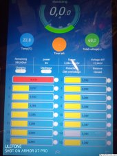
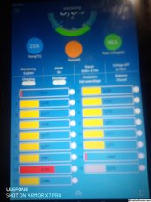
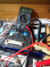
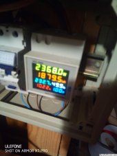
[06:54, 9/11/2023] Alvaro Nannicini: Hi, the problem of my bms is the voltage detection on cell n'1 {tension measured by bms}. The cell 1 {B1} voltage is 3.2v, but the bms indicates the voltage equal to 15v.
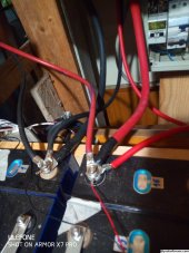
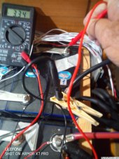
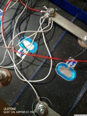
I check several times the wirings ,but these are perfect. I tried also to measure the real voltage between BO and B1 on the bms board ,through a multimeter, and this is 3.2v.
So i think the problem is in the internal bms' hardware because instead of 3.2v, the bms shows 15v.
I attached also a picture with the voltage shown by bms through the app.

What we gonna do?
[07:08, 9/11/2023] Alvaro Nannicini: Many people are following this issue
[07:11, 9/11/2023] Jane Lee: Can you use our latest app?
[07:11, 9/11/2023] Jane Lee: Search xiaoxiangElectric on Google APP Store or Apple APP Store and you can download our latest APP.
[07:11, 9/11/2023] Jane Lee: it's small elephant sign
[07:12, 9/11/2023] Jane Lee: And give me the picture,is that ok?
[07:15, 9/11/2023] Alvaro Nannicini: I use this one
[07:17, 9/11/2023] Jane Lee: Not this
[07:18, 9/11/2023] Jane Lee: Can you give me the picture?
[07:32, 9/11/2023] Jane Lee: Can you give me a complete screenshoot?
[07:32, 9/11/2023] Jane Lee: Thank you very much.
[07:36, 9/11/2023] Jane Lee: Dear, can you measure the actual voltage of the first series of batteries is 18.25v?
[07:43, 9/11/2023] Jane Lee: Can you try current calibration?
[07:43, 9/11/2023] Jane Lee: It's on the "Function" page
[07:44, 9/11/2023] Jane Lee: Parameter
[07:46, 9/11/2023] Alvaro Nannicini: I Need to setup the password, I need time
[07:47, 9/11/2023] Jane Lee: Ok,dear.
[07:53, 9/11/2023] Jane Lee: Nominal capacity is actual capacity, cycle capacity is 80% of nominal capacity, please set according to your actual battery capacity.
[07:59, 9/11/2023] Jane Lee: And then?
[08:09, 9/11/2023] Alvaro Nannicini: I have already done all these tests with experts on the forum and BMS experts on YouTube, now it's time for breakfast, then I'll find what you want to know, of course if you tell me that I can't use this 200 A BMS because my batteries are 280 A and I have to use smaller batteries I think it's difficult to carry on :), I'll talk to you later.
[08:12, 9/11/2023] Jane Lee: Ok,dear,sorry,pls work on your thing.
[09:57, 9/11/2023] Jane Lee: Excuse me,dear, you mean 280a battery capacity? What is the power of your motor, what is the continuous current A, what is the peak current A?
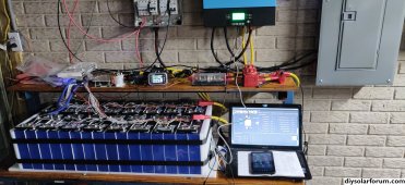
[10:22, 9/11/2023] Alvaro Nannicini: If you reread the chat from the beginning you will see that I have already replied, I sent you the link of my inverter where you can find all the features, the batteries are 280 A, 16 s, 48 V system and inverter, My system is 48V, my inverter is 6kw so A = 6000w: 48 = 125A therefore the maximum that the inverter can draw from the batteries is 125 A continuous current.
[10:25, 9/11/2023] Jane Lee: if the 125a is the maximum continuous current, you can use this battery, I thought your maximum continuous current is 280a
[10:25, 9/11/2023] Jane Lee: You can try using the app to calibrate the current first, dear.
[10:38, 9/11/2023] Alvaro Nannicini: I wrote it down for you and also put the formula
A= W/V therefore 6000w: 48 V = 125 A.
If we continue like this we will get to Christmas, your time for writing will be paid as work, but mine will not, I have already done all the possible tests, the parameter settings are correct and all the experts with whom I have shared the problem have said that this BMS does not work.
[10:43, 9/11/2023] Alvaro Nannicini: You can see in this video if you find something you want to know, it's just part of the tests.
[10:46, 9/11/2023] Alvaro Nannicini: When I read something that I don't understand I ask expert friends for help, I think it's appropriate for you to do the same thing, ask some technician in your company.
[11:32, 9/11/2023] Alvaro Nannicini: Your beautiful personalized box that arrived without instructions but not even a post it with a support URL written from the "official" JBD reseller is ready to be sent back to the sender. If this is the situation it is preferable not to buy on AliExpress.
 
Back
Top