diy solar

diy solar

Solis S5: Various issues

Modbus -> laptop -> python -> mqtt -> clickhouse -> grafana

1674128148792.png

Main house meter is Eastron SDM630 which is quite fast, it updates its power reading in less than 0.2 seconds (here the water heater was turned on and off). So it can be used to drive the future power router without any issue.

The inverter is much slower to react, takes up to 5 seconds to catch up. There's probably a parameter for that somewhere in those undocumented registers... I wish it would query the meter more often than once per second.

Clickhouse is nice to store time series data, I put all the MQTT stream into it, and it achieves a compression ratio of 12x. It also coalesces data into materialized views, to speed up queries on long time ranges...
 
For some reason the battery charging current seems to be limited to 66A. This is visible on the plot above: on the left, yellow trace "battery power" is flatlining at 3.5kW, and it is exporting instead of charging harder. I thought the inverter could charge at 100A... Battery BMS sets the limit to 160A so it should not be the problem. Any idea?
 
The Orange Pi has arrived! It works great.

I'd like to emulate an Acrel ACR10RH meter, but it contains some reserved registers... and without those values the Solis will not recognize it.

If anybody has one and could dump registers 0-65 fcode 3 that would help a lot! lol
 
Strike that, I reverse engineered Acrel registers, it's emulated now.
For some reason, Solis only queries power from Eastron meter every 2 seconds, but it queries from Acrel every second.
So it adjusts its exported power twice as fast with Acrel meter...

The meter can be queried about 10 times/second, so it's really not breaking a sweat lol
 
Got fed up with Grafana, too damn slow. I tried Bokeh, much better.

 
All good detective work. Let us know if it powers up automatically when get PV again. Also, have you measured how much battery consumption reduces by when you put it in sleep mode?[/URL]
Extremely low, a few watts or less.
However when in sleep mode it cuts off the backup output, so I added an external DPDT contactor to switch backed-up loads between grid and backup output.
 
Solis EH1P-6K teardown time! With pictures!

Turns out the recurrent fan alarm had something to do with the delivery man throwing the inverter in its box over my 2 meter high fence... quite the feat lol.

Would love to see your teardown but malheuresement-ly I don't seem to avez les correct permissions to see any of your fichiers :)

"Vous n’avez pas les permissions nécessaires pour voir les fichiers joints à ce message."

Any chance of posting them here quand vous avez un moment?
 
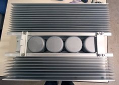
Alright! That's the heat sink, but you've seen it already.
IMG_20230205_182718.jpg

The cylinders in the center are the magnetics, MPPT inductors, and probably two transformers for the 48V battery converter.

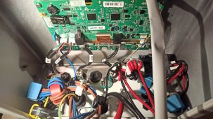
The whole inverter case is a single piece screwed on the heat sink, there's a seal for IP68 rating. It opens easily, here's the connector panel, normally at the bottom of the inverter, seen from the inside.

IMG_20230205_183107.jpg

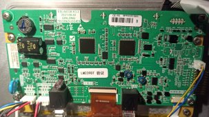
The board is the LCD controller, it also handles all communications (meter, modbus, CAN, etc) which do not seem to be isolated, no special filtering either. It is linked to the power board via a 10 pin ribbon cable (top right). They put protection diodes on the cable to the power board. The grid port CT is on this board, but not the voltage measurement, which explains why the grid port power measurement is not very accurate...

IMG_20230205_183128.jpg

Besides that, nothing special to say about the board, it's not possible to read the part numbers due to the waterproofing varnish.
 
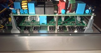
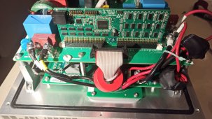
Bolted on the heat sink are two power boards, mounted mezzanine style with extremely chunky reinforced standoffs, plus plenty of normal board standoffs. That explains why nothing broke or fell off when the delivery man threw the inverter over the fence! lol

IMG_20230205_183951.jpg

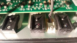
Nice mounting of power semiconductors with "Ginlong" branded plastic clips. Apparently they read that famous appnote: the screw hole in these transistors is not the best way to mount them, it is better to apply pressure on the center of the silicon die with a clip (usually spring steel) to avoid one side being pressed against the heat sink more than the other which creates hotspots. This right angle mounting style also lets the legs bend a little bit with thermal dilatation, unlike vertical mounting which sometimes ends up pushing the pads out of the circuit board when the legs get hot (and therefore longer).

IMG_20230205_183945.jpg

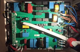
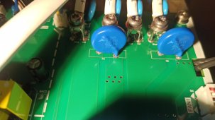
Now the top board which contains filtering, current measurement and relays.

IMG_20230205_183216.jpg

This is probably the DSP board that drives everything...

IMG_20230205_183419.jpg

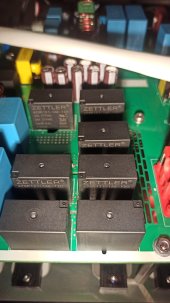
Now looking a bit more closely, the inside of this inverter is a damn fashion show, all big name brands everywhere: big ZETTLER 35A relays...

IMG_20230205_183501.jpg

Pretty much all the little caps are United Chemi-con 105°C, brown ones are KY series, only 2-3 Chinese caps on the whole board, also 105°C rated. All the film caps are EPCOS, there's a ton of them, even the damn MOV's are EPCOS not no-name stuff...

IMG_20230205_183525.jpg

Copper on this board is really thick, probably 2oz according to my calibrated fingernail, they didn't skimp on the stuff!

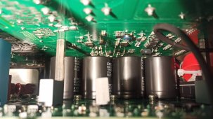
Lower level of the mezzanine, all the HVDC bus caps are EPCOS again...

IMG_20230205_183816.jpg


Nice PCB wire to board terminals with everything done right, crimped sleeved etc. The big toroid inductor cores are wrapped with insulating foil, not just counting on the paint to prevent shorting the wire coil if vibration rubs off the insulation... lots of nice details, this is definitely not Voltronic :ROFLMAO:

All the screws are stainless, even inside, and the washers too. Magnetic screwdriver is useless, I had to hunt for one under the sofa.

It's not possible to say much about the circuitry because it's all SMD on the bottom side, so it's not visible without disassembling everything, and I'm only in there to fix the fan alarm.
 
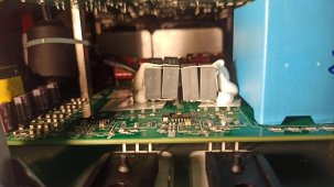
And suddenly... a disgusting bodge! Looks like they ran out of caps and had to hand solder smaller one to make bigger ones...

In the background there's a huge herd of film caps which hints at the 48V conerter being a resonant design.

IMG_20230205_183900.jpg

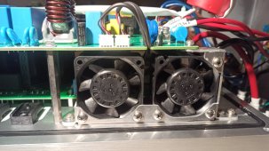
And we reach the goal of this expedition! Yes indeed this fanless inverter has two fans inside, which provide some extra cooling on the 48V converter. They're only moving air inside the enclosure, not in contact with outside air. The downside is they mostly blow how air, but that spreads the heat inside and uses the whole enclosure as a heatsink, not just the back.

IMG_20230205_184157.jpg

The fan on the right got a bit crushed when the inverter landed on my lawn, so I filed off about 0.1mm of plastic that blocked the blades, and now it turns smoothly. Battery charging current is no longer limited to 70A, it reaches the full 100A, and it no longer complains about fan alarms.

Conclusion: OK it's a Chinese inverter but the parts quality level is absolutely excellent and it looks well built. Victron's gonna have to shave off their prices a bit lol.

Some of the design is a bit weird like the fan blowing hot air inside the enclosure, that feels like a late addition to the design. I wonder if the new S6 version will still have it...
 
Fantastic - merci beaucoups :) Good to see how well it's built.
 
The record so far:

8kw solar input -> 5kW battery charging + 3kW export (not bad for a "6kW" inverter)...

...However, the inverter reports an internal peak temperature of 75°C, yikes!

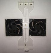
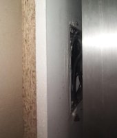
Since it is mounted on a large board along with the rest of the electric gear, I mounted the board 3cm away from the wall, cut two square holes in the board behind the inverter, and inserted two Arctic P12 PC case fans right behind the inverter heat sink. They suck air from behind the board and blow it on the heat sink. So the fans are mounted vertically and in cool air, which is best for bearing life.

-> At full power, peak inverter temperature 45°C, much better.
 
Fans installation:

fan mount 1.JPG

Side view with inverter heat sink (inverter mounted on board which is installed ~3cm away from wall):

fan mount 2.JPG


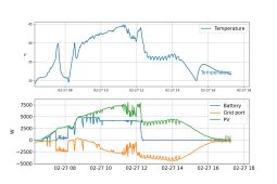
Inverter internal temperature (modbus), no fans, at 7kW peak power, very hot:

no fan.JPG

With fans: 45°C peak at 7.5kW, much better:
2x Arctic P12 behind.JPG
 
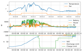
Previously the fan was set to start when inverter self-reported temperature exceeds 40°C and stop when it cools down to 30°C.

In this inverter, most of the heat comes from the battery DC-DC. So I also set it to run the fan when battery power exceeds 2kW. This gives it a head start, as it doesn't have to wait until the huge mass of the heat sink is hot to start blowing air. This gives nice results, the inverter sure is a lot less toasty than before.

1677793160815.png
 
I measured the idle power use.

Inverter is ON, grid is disconnected. Backup output is enabled and it is delivering 240VAC without load.

I measured current draw on the battery with an Aliexpress shunt and a multimeter on 200µV range. Also voltage of course.

-> 50V 1.12A = 56W power consumption from battery.

Margin of error +/-10% because the display was fluctuating a bit. It's not exceptional, but it's not bad either.
 
Modbus -> laptop -> python -> mqtt -> clickhouse -> grafana

View attachment 130430

Main house meter is Eastron SDM630 which is quite fast, it updates its power reading in less than 0.2 seconds (here the water heater was turned on and off). So it can be used to drive the future power router without any issue.

The inverter is much slower to react, takes up to 5 seconds to catch up. There's probably a parameter for that somewhere in those undocumented registers... I wish it would query the meter more often than once per second.

Clickhouse is nice to store time series data, I put all the MQTT stream into it, and it achieves a compression ratio of 12x. It also coalesces data into materialized views, to speed up queries on long time ranges...
Hi, I want to implement a similar graph. Can you tell me the mapping between the sensors and RS485 registers ?
Basically I want something like the attached graph in real time.
Thx
 

Attachments

  • Capture.JPG
    Capture.JPG
    80.8 KB · Views: 5
Hi, I want to implement a similar graph. Can you tell me the mapping between the sensors and RS485 registers ?
Basically I want something like the attached graph in real time.
Thx
All the code: https://github.com/peufeu2/GrugBus

Modbus mappings are in grugbus/devices

If you want to ask the inverter for what the smartmeter is measuring, see registers 33251 and following

My code to query the inverter is in modbus_mitm.py, start reading at line 633 for the inverter stuff.
 
Is there a possibility to set the charge current on Solis S5-EH1 / Pylontech ?

I like to to implement dynamic charging for two reasons:
1. Make the most out of the 8 kW DC capability
2. To not have the battery on 100% SOC at 11:00 CET in summer

As far as I understand until now, the register ist forbidden to write. Am I wrong ?
 
Yes that is possible. The Solis will charge at the rate specified in each CANBus message, typically sent once a second. I use it to dynamically change current based on SOC and temperature, as mentioned here...


Charge voltage and current are sent in CANBus message 0x351.
 
Yes that is possible. The Solis will charge at the rate specified in each CANBus message, typically sent once a second. I use it to dynamically change current based on SOC and temperature, as mentioned here...


Charge voltage and current are sent in CANBus message 0x351.

So I need a way to modify the CANBus messages between Solis and Pylontech ?
Something like a man in the middle ?
 
That would be a possible solution. I have DIY battery, not Pylontech, so it was simple for me to implement ?‍?.

I wonder though whether the Pylontech's charge rate is configurable via the pylontech admin console port? If so, then you could programmatically instruct the pylontech to charge at a different rate.

Or maybe it is possible via ModBus over the RS485?
 
I like to to implement dynamic charging for two reasons:
1. Make the most out of the 8 kW DC capability
2. To not have the battery on 100% SOC at 11:00 CET in summer
What's the end goal? I mean what's the problem if the battery is charged?
 
Or maybe it is possible via ModBus over the RS485?


Official register:
33206 U16 0.1A Battery max charge current

Scheduled charge:
43141 U16 0.1A Timed charge current
43142 U16 0.1A Timed discharge current

Undocumented:
43116 U16 0.1A Battery charge and discharge current setting
43117 U16 0.1A Battery charge current maximum setting
43118 U16 0.1A Battery discharge current maximum setting

Some of the battery current registers are not usable because they're constantly overwritten by the value from the BMS, so if you write something it'll just be overwritten immediately. I think this is not the case for the above ones.

If you want to make frequent writes you should make sure these registers are not saved to flash memory, otherwise you'll use up the flash endurance. You can do that by writing a different value, then turning off the inverter completely (battery, grid, PV...) wait... then restart it... and check if the value was saved or not.
 

diy solar

diy solar
Back
Top