diy solar

diy solar

Grounding 110V outlets

almostalx

New Member
Joined
May 8, 2020
Messages
13
Hi there!

I'm finalizing a van build and I just realized that I made a mistake. I ran all the wires for my appliances, but I forgot about the AC outlet ground. Normally I would've used a 12/3 wire from the inverter to the 2 outlets that I have, but when I did my wiring I forgot about the ground and used a 12/2 wire. My walls are closed now and it would be a real pain to re-open and change the wires for those 2 outlets. It might be a dumb question, but can I ground the 2 outlets to the van chassis and call it a day? Or do I really need to ground the outlets in the inverter?

Thanks for the tip!
 
I'm not sure what you mean by 'the white wire'. My wires are red and black. My inverter is grounded to the chassis, but my question was whether or not I could do the same with the outlets of I hav to ground them on the inverter ?
 
I'm not sure what you mean by 'the white wire'. My wires are red and black. My inverter is grounded to the chassis, but my question was whether or not I could do the same with the outlets of I hav to ground them on the inverter ?

So which one is neutral and which one is hot?
 
I used red for hot and black for neutral, even though it's not the same color code as you see inside houses. I labeled so it's easier.

I'm not sure what you mean, I don't deviate from 12V and I don't own a tesla haha. My system is a 12V battery that goes into a 2000W Renogy inverter. Then the AC 110V side of the inverter goes to 2 electrical outlets further in the van. My question is whether or not these 2 outlets can be grounded to the chassis (I'm pretty sure they can) or I absolutely need to ground them on the inverter. My guess is it's equivalent since the inverter is grounded on the same chassis anyway.
 
Does your inverters manual say that it needs to be grounded? Some can be left with the AC circuit free floating and independent from the vehicles systems. I hesitate to say to much as not only am i not qualified but I am from the UK which might makes things different.

I am fairly sure though that grounding your AC circuit to the vehicle chassis is a bad idea, it should be kept separate from your DC equipment and the vans own electrics.
 
The manual asks for the inverter to be grounded to the chassis on the DC side, but it doesn't say anything about the AC side. I guess I can write them an email asking for that. But I kinda doubt that they'll known themselves (from my experience with Renogy support).
 
The manual asks for the inverter to be grounded to the chassis on the DC side, but it doesn't say anything about the AC side. I guess I can write them an email asking for that. But I kinda doubt that they'll known themselves (from my experience with Renogy support).


The manual for mine specifically states the AC side needs grounding for safety and there is a seperate connector on the AC end of it for this purpose, if yours doesn't say the same it may be OK but good idea to check with the manufacturer.

Mine is not a renology inverter, i just use it as an example.
 
The correct grounding procedure will depend on weather your inverter has the neutral and ground bonded inside the inverter.
 
The correct grounding procedure will depend on weather your inverter has the neutral and ground bonded inside the inverter.

Thanks for making me think about it.
If an inverter has hardwire capability I would think it would not be bonded internally by default.
@almostalx Is your inverter designed for hardwire?
Either way, is their continuity between N and G on the inverter?
 
My new inverter actually can switch internally between bonded and not to accomodate the conditions "downstream". In other words, if your main/sub panel is bonded, and you'd rather un-bond the inverter than change panel wiring, you can. Probably mostly useful for older distribution boxes, as new ones are easily bonded/unbonded with a screw.
 
My new inverter actually can switch internally between bonded and not to accomodate the conditions "downstream". In other words, if your main/sub panel is bonded, and you'd rather un-bond the inverter than change panel wiring, you can. Probably mostly useful for older distribution boxes, as new ones are easily bonded/unbonded with a screw.
What make and model?
I know the Samlex evo does this I wonder how many others do.
 
My new inverter actually can switch internally between bonded and not to accomodate the conditions "downstream". In other words, if your main/sub panel is bonded, and you'd rather un-bond the inverter than change panel wiring, you can. Probably mostly useful for older distribution boxes, as new ones are easily bonded/unbonded with a screw.
No disrespect but when you go from ground to talking about bonded and unbounded you lost me and maybe alot of others keep in mind we are diyers
 
I
No disrespect but when you go from ground to talking about bonded and unbounded you lost me and maybe alot of others keep in mind we are diyers

It's a very important safety issue that you need to understand if you plan to hardwire an inverter, and it is ALL about grounding. No disrespect, but it's worth a google search and some reading if you want to do things correctly and safely.
 
The ground pin on the receptacle must have a path to neutral at the inverter. If the device that you have plugged into the receptacle has a short to the housing and there is no path to the inverter you have 120 volts on the housing. By having a path you blow the fuse or trip the breaker. None of this matters if the devices you are going to use are two wire (no ground pin). Some two wire devices bond the housing to the neutral others the housing is plastic or some other none conductor. I agree that you should be able to get information from the company that built the inverter and then follow that information. One other option is to install a gfci receptacle in the first location and then use that to protect the second location. If you may connect to shore power or a generator you want to get some advice from someone who deals with rvs. If you are confused about grounded and bonded you are part of a very large group.
 
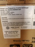
I just say a picture of the bottom panel on a mpp solar unit and there was no ground terminal for the ac out. I am sure that when Will did a video that unit did a ground connection for ac out. There is probably a simple answer but I sure don't know what it is.
 
I found this video on youtube. This guy does a great job explaining it. Hope it helps.

 
Thank you for ex
The ground pin on the receptacle must have a path to neutral at the inverter. If the device that you have plugged into the receptacle has a short to the housing and there is no path to the inverter you have 120 volts on the housing. By having a path you blow the fuse or trip the breaker. None of this matters if the devices you are going to use are two wire (no ground pin). Some two wire devices bond the housing to the neutral others the housing is plastic or some other none conductor. I agree that you should be able to get information from the company that built the inverter and then follow that information. One other option is to install a gfci receptacle in the first location and then use that to protect the second location. If you may connect to shore power or a generator you want to get some advice from someone who deals with rvs. If you are confused about grounded and bonded you are part of a very large group.
 

diy solar

diy solar
Back
Top