diy solar

diy solar

JK BMS Active Balancing

I have 3 x jikong BMS, 200A 2A balancing, on 3 x 260Ah BYD 51.2v battery packs (actually 6* S8)

"Identical" as can be, all with the same cable length.
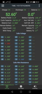
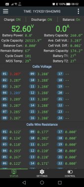
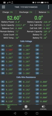
Screenshot_20230629_080253.jpgScreenshot_20230629_080258.jpgScreenshot_20230629_080310.jpg

As you can see the cycle capacity is not the same.
My best explanation is that the total resistance per battery set is slightly different.

I also needed to adjust the voltage at start between the 3 BMS.
That's why there is a "calibrating voltage" setting :)

Use a reliable multimeter and test with the packs balanced and in rest.

Correct any offset... Done.

I've noticed that some of the 6 units charge a tad faster then the others, giving it some difference.

Nothing crazy.

Again, in my humble opinion..
Minor internal resistance difference.

I used a torque meter to have the terminals clamped with the same compression, yet...
So many things might give a slightly better or worse contact, different resistance.

10% cycle count difference is a "lot".
Yet..
In 2 years roughly 125 cycles per set.
Lithium is built for +3000 cycles
Or roughly after 50 years this would become an issue?

So I don't mind.

For OP..
As most suggested...
Start top balancing first!

Don't be a wuss...
Take your time for this.
If you are (like most) are charging on solar..
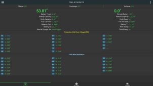
Your balanced pack should look like this in the early morning, before charging.. (so after +5 hours rest)
IMG_20230629_081755_894_edit_271194965819671.jpg
(Yes, Thailand it's dark at 19.00)
(Yes, my friend who made this screenshot should have been sleeping at 02AM ?)

Anyways...
This is what a good top balanced pack looks like.
He wasn't in hurry, and accepted that the absorption will take a DAY(!!) (Or more) to have a really good top balanced pack.

Once both sets are balanced...
measure the voltages with a multimeter.
Probably the same.
If not, check your connections..
some might be less optimal.

And please let us know how it is progressing!!
 
Last edited:
My suggestions are as follows:
Top charge & Top balance your cells to at least 3.600 and allow the charge to drop to at least 14A but you can let it go down to 5A but don't go lower.

Bulk/Absorb Voltage should be 55.2 Volts (3.450V per cell.)
EndAmps/TailCurrent is 14A, the point where ti switches from Bulk/Absorb to Float
Set Float to 55.1 Volts (3.443V per cell)

Set your Active Balancing to start @ 3.200 !
- Active ONLY MOVES power from a high cell to a low cells. It only does this when the Differential limit is reached.
- Starting at a lower voltage reduces the work as it is charging so when reaching above 3.400 and cells start to deviate (as expected) the amount to move about is much less.
!! Active Balancing does NOT waste power like passive balancing, when cells are within the diff threshold the balancer is inactive.

My experience is with 6 packs in Parallel using JK's. I have done extensive tests and thrash tests and sorted these things out. Also as an FYI, I am the same Steve_S that wrote their manual. Please look at my signature for more info, charts, and the settings I use.

Lastly, I need to point out that LFP like all chemistries has two voltage ranges.
The Allowable Range (2.500-3.650) is the range that the voltage will not cause harm or damage to the cells. Below or Above that range causes harm.
The Working Voltage Range is from 3.000-3.400 which is the LFP Flat Curve that delivers the Actual Amp Hour Rating, IE the 280AH from your 280AH Battery. This is why the Nominal Voltage of LFP is 3.200 (50% SOC). A Standard A Grade 280AH Cell will deliver 280AH NET (from the working range) but till typically test out at 288-292 AH Gross if tested from 3.650 down to 2.500 volts.

ASSEMBLY ISSUES = Weird Problems.
When assembling the cells, you need to clean off the contact surfaces as they often have a light wax/oil on them to prevent corrosion.
Bus Bars need to be perfectly flat, with no Burrs or Ridges at the holes, if there are file them off.
Clean everything with Rubbing Alcohol !!!
You can apply a Very Light dab of No-A-Lox or similar on the flat surfaces to prevent corrosion... DO NOT put any on the threads, it acts like a grease.
Torque the screws/nuts to 5nm.

All of the above factors can affect the IR readings, charge/discharge issues (hot terminals is one example) and more.

Hope it helps, Good Luck
Torque the screws/nuts to 5nm....

That highly depending if you have the laser welded studs or the cells where the seller made their own threads by hand .. (usually crappy quality)

3.5 is "safe"
4.0 is pushing it
4.5 , especially when it's the second time you fasten... Danger zone
5 nm... You might be in trouble!

This al depending on how you prepared the studs.

Loctite red (with activator) or even stronger jb-weld...
Yes, the 5nm is a good tight clamping strength

Just SS studs you threaded inside and can feel wiggling in the crappy made treads from the seller?,

3.5-4nm , max!!

You need to go a few years back to find my extensive post in how to drill and re-tap with M8, the tests with inserts, different brands and types of epoxy and all kinds of "repair"...

That I obviously didn't wanted to do..
Yet...
Just a tiny bit over 3.5Nm back then, with no additional preparation like loctite...
Stripped treads...
Eve 152Ah and 280Ah's were crap back then!

Skew treads, half treaded, too deep so you can see the copper inside the hole, and usually...
Way to weak to tighten properly.

Those where the pioneering years :)

Anyway... Laser welded?
Yes! 5Nm.

And do spend this $25 on a simple digital torque meter!!! (AliX)

That will save you so much trouble!
Also fun to test how good your "hand measurement" really is.

I've hold wrenches the better part of my life.. and thought I can feel pretty accurate the same torque strength.

Turns out....
One has quickly a whole Nm difference...
Even with "light torque" like this.
 
My suggestions are as follows:
Top charge & Top balance your cells to at least 3.600 and allow the charge to drop to at least 14A but you can let it go down to 5A but don't go lower.

Bulk/Absorb Voltage should be 55.2 Volts (3.450V per cell.)
EndAmps/TailCurrent is 14A, the point where ti switches from Bulk/Absorb to Float
Set Float to 55.1 Volts (3.443V per cell)

Set your Active Balancing to start @ 3.200 !
- Active ONLY MOVES power from a high cell to a low cells. It only does this when the Differential limit is reached.
- Starting at a lower voltage reduces the work as it is charging so when reaching above 3.400 and cells start to deviate (as expected) the amount to move about is much less.
!! Active Balancing does NOT waste power like passive balancing, when cells are within the diff threshold the balancer is inactive.

My experience is with 6 packs in Parallel using JK's. I have done extensive tests and thrash tests and sorted these things out. Also as an FYI, I am the same Steve_S that wrote their manual. Please look at my signature for more info, charts, and the settings I use.

Lastly, I need to point out that LFP like all chemistries has two voltage ranges.
The Allowable Range (2.500-3.650) is the range that the voltage will not cause harm or damage to the cells. Below or Above that range causes harm.
The Working Voltage Range is from 3.000-3.400 which is the LFP Flat Curve that delivers the Actual Amp Hour Rating, IE the 280AH from your 280AH Battery. This is why the Nominal Voltage of LFP is 3.200 (50% SOC). A Standard A Grade 280AH Cell will deliver 280AH NET (from the working range) but till typically test out at 288-292 AH Gross if tested from 3.650 down to 2.500 volts.

ASSEMBLY ISSUES = Weird Problems.
When assembling the cells, you need to clean off the contact surfaces as they often have a light wax/oil on them to prevent corrosion.
Bus Bars need to be perfectly flat, with no Burrs or Ridges at the holes, if there are file them off.
Clean everything with Rubbing Alcohol !!!
You can apply a Very Light dab of No-A-Lox or similar on the flat surfaces to prevent corrosion... DO NOT put any on the threads, it acts like a grease.
Torque the screws/nuts to 5nm.

All of the above factors can affect the IR readings, charge/discharge issues (hot terminals is one example) and more.

Hope it helps, Good Luck
I think this is a good starting point for me to learn through this process and see if I can get things balanced. Appreciate the feedback and I'll post here again if I still can't resolve balancing.
 
I think this is a good starting point for me to learn through this process and see if I can get things balanced. Appreciate the feedback and I'll post here again if I still can't resolve balancing.
Much of what I said and more is within this resource I wrote a while back. Download that and I'm sure you'll find it handy.
Luyuan Tech Basic Lifepo4 Guide V1.0A
 
Much of what I said and more is within this resource I wrote a while back. Download that and I'm sure you'll find it handy.
Luyuan Tech Basic Lifepo4 Guide V1.0A
Thanks Steve! Much appreciated!
Even an old timer like me found some "new stuff" or at least a refreshing of knowledge:)

What I didn't see in the document is adviced torque (Nm) for the studs.

My personal playground with a few pillowed 280 cells (I had an "oeps") a well prepared stud (I re-tapped to M8) locked in place with JB-weld (just a tiny bit on the threads inside the terminal, and don't forget to "OCD" clean the treads on stud and terminal prior to the JB) is that the terminal itself will start rotating at 9Nm.
(Some higher, never lower)

People don't need to be afraid for this :)

My advice for torque specs:

3.5Nm if you hardly prepare and use standard grub screws/studs. Hand tight, then a twist back (the stud) before you tightening the nut ?

4.0 Nm if you do some preparation.
Clean the studs and threaded terminals with alcohol or acetone, and use loctite (Red) + let it "harden" for 24 hours.

4.5 Nm when you use activator prior using loctite.
Stainless steel and aluminum both need activators.. without them, your bond is as "strong" as cheap super glue.

4.5 Nm and (slightly) up) after OCD cleaning and quality epoxy like JB Weld (JB is a bit stronger then activated loctite)

Loctite thread repair isn't strong enough!!! (Expensive! And gives at 3.5-4Nm)
And.. after stripping the threads (a bit) JB weld might safe the day. (Up to 4Nm)

If you feel absolutely no grip from the stud... No real treads left..
JB weld might help up to 3.5Nm.
(Also depending on your cleaning skills)

Stripped 6mm can be directly re-tapped with 7mm (if you can find the studs) and sometimes even 8mm

You can use any commercial available set, the aluminum is soft.
BUT: modify the taps.
Usually they come as 3 steps, or a "3 in one).. and have a longer tapered end.

As result you can't tread the lower section.

Hacksaw or grinder is your friend and cut the tapered part AFTER you "pre tapped" them
Best is to get the 3 step tap, or buy 2 and make the second to be used as a "bottom tap".

Yes, they can be bought as bottom tap.
A cheap China set will cost like $5
Bottom taps I never found cheap..

For re-threading (tapping) watch some YT videos.
By hand is fine.

If you have a drill stand, even better!
Move the head by hand, not electric.
Half turn in, 1/4 back, 1/2 turn in, 1/4 back.
When at 3/4 depth, all the way out, clean inside and do the last part in 2 sessions.

Don't forget to use oil when tapping.
It might not feel you need it.
Your end result will be more smooth and threads stronger.

Afterwards... Clean clean clean

Your terminal probably got a ridge after tapping.
Please do remove.
A hobby knife is strong enough, chamfering tool is more safe.

And if you didn't learn the first time.

Yes.. use loctite AND activator, even with M7 or M8

And clean clean clean...
Good clean flat surfaces will help you a lot!!!

Sidenote:
I was wondering if using loctite or epoxy would interfere conductivity of the stud.
For measuring purposes:
Absolutely the same voltage.

I would not try to pull (or push) high capacity via the stud, it obviously will have lost some conductivity.
For measuring...
The same (0.0001 my meter doesn't have a lower setting)

Second sidenote:
Temperature.
Loctite red (when used with activator) is the preferred choice.

Even in the wierd situation that your terminal reach +100c, no difference in contact strength.

JB weld (and most other epoxy) get somewhat flexible at higher temperature.
Cheap ones at +60 (even had a cheap one at 50c !)

JB should stay strong even above 100c

just a reminder..
if you used lesser quality epoxy, you are fine, as long as you don't use too high current and not too high environment temperature.

loctite red? (With activator!)
Up to 250c... You are good to go.
your cells probably won't be.
 
Last edited:
My suggestions are as follows:
Top charge & Top balance your cells to at least 3.600 and allow the charge to drop to at least 14A but you can let it go down to 5A but don't go lower.

Bulk/Absorb Voltage should be 55.2 Volts (3.450V per cell.)
EndAmps/TailCurrent is 14A, the point where ti switches from Bulk/Absorb to Float
Set Float to 55.1 Volts (3.443V per cell)

Set your Active Balancing to start @ 3.200 !
- Active ONLY MOVES power from a high cell to a low cells. It only does this when the Differential limit is reached.
- Starting at a lower voltage reduces the work as it is charging so when reaching above 3.400 and cells start to deviate (as expected) the amount to move about is much less.
!! Active Balancing does NOT waste power like passive balancing, when cells are within the diff threshold the balancer is inactive.

My experience is with 6 packs in Parallel using JK's. I have done extensive tests and thrash tests and sorted these things out. Also as an FYI, I am the same Steve_S that wrote their manual. Please look at my signature for more info, charts, and the settings I use.

Lastly, I need to point out that LFP like all chemistries has two voltage ranges.
The Allowable Range (2.500-3.650) is the range that the voltage will not cause harm or damage to the cells. Below or Above that range causes harm.
The Working Voltage Range is from 3.000-3.400 which is the LFP Flat Curve that delivers the Actual Amp Hour Rating, IE the 280AH from your 280AH Battery. This is why the Nominal Voltage of LFP is 3.200 (50% SOC). A Standard A Grade 280AH Cell will deliver 280AH NET (from the working range) but till typically test out at 288-292 AH Gross if tested from 3.650 down to 2.500 volts.

ASSEMBLY ISSUES = Weird Problems.
When assembling the cells, you need to clean off the contact surfaces as they often have a light wax/oil on them to prevent corrosion.
Bus Bars need to be perfectly flat, with no Burrs or Ridges at the holes, if there are file them off.
Clean everything with Rubbing Alcohol !!!
You can apply a Very Light dab of No-A-Lox or similar on the flat surfaces to prevent corrosion... DO NOT put any on the threads, it acts like a grease.
Torque the screws/nuts to 5nm.

All of the above factors can affect the IR readings, charge/discharge issues (hot terminals is one example) and more.

Hope it helps, Good Luck
Set your Active Balancing to start @ 3.200 ! --- is this correct?
i thought this will unbalance the cells, that has been the general understanding.

everyother thing is ok to me. i torque my cells to 7nm and it remains rock solid
 
Regardless of what voltage the Active Balancing is set to start, it will only "move" energy from a cell above the threshold to the lowest voltage cell. If the cells are within the allowable deviation (typically 10mv) Active balancing does nothing. It does NOT waste any energy.
 
If I'm in the wrong subforum, please redirect me...

I have two 16cell LifePO4 280ah battery packs connected with 2 200a JK BMS' (b2a20s20p). I've noticed that the voltage between the two is not that close. I have identical settings (at least the ones I could set) in the JK app. There's also some difference between each cell (more than I think there should be). I noticed that battery pack #2 is also showing more cycles than battery pack #1 (but I believe I had battery pack #1 added first).

Trying to understand how to get these more aligned on voltage and how to lower the cell difference in voltage per pack. Let me know if I can provide any more details around the setup.

Any suggestions?

Thanks in advance!


Battery Pack 1 Status and Settings:

View attachment 154667View attachment 154668

Battery Pack 2 Status and Settings:

View attachment 154671View attachment 154672
If still having issues, use an active balance circuit. It makes a big difference on the bigger cells.
 
Why does the "max balance current" amperage seem to be "stuck" at .4a on the JK BMS? If I bump this up at all, it gives the me the failed to send error msg. Even goign to .5a. Is another parameter tied to this that is stopping me from selecting higher amperage?

Thanks
 
Back
Top