diy solar

diy solar

Cut bus bars in an existing breaker panel

Delmar

Solar Addict
Joined
Dec 9, 2019
Messages
942
Location
Lake Conroe Texas
Humor me on this one. The intent is how to isolate critical/grid-down circuits in an existing breaker panel without major surgery to the wall, and safely isolate backup-power from grid power. And be reversible should I ever sell the house.

I have a 3000VA UPS being used as a grid-down inverter that back-feeds the panel. The UPS has an integral transfer switch and float charger that are currently not being used. I have a golf cart with 48V mobile battery set, and planning to purchase a 2nd 48V stationary battery set.

My existing breaker panel is only around 50% capacity. How dangerous would it be to cut the existing bus bars midway-panel and move any critical circuits (fridge, lights, master bedroom plugs) to the lower part of the panel? Then critical circuits would be constantly powered through the UPS, and safer than my manually sequencing the breakers. Please reference the following sketch.
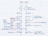
breaker panel.jpg

During grid-down would allow me to have one battery set inside powering the house, and one set outside charging from the panels. Can also lift the UPS onto the cart and drive to a nearby family home and briefly power their fridge.
 
interesting idea; it isn't code but it would probably work. although I'm not sure your current / breaker totals are correct. IE: one 30a breaker feeding in to two 20a breakers. but you're probably thinking that the down stream circuits won't approach the 30a total. I'm essentially doing the same in my 5th wheel; where one entire leg of the 50a supply has the inverter in it. All the circuits that I want on the inverter for off grid use have been relocated on that entire leg of the panel.
 
The bussbars in panels are usually clipped in place, cutting them likely wouldn’t leave them in usable condition...

it’d be better to use a second sub panel for the loads...
 
I thought about doing this, and got as far as disassembling a new panel and marking where to cut. I ultimately went with multiple panels and disconnect switches, all to code. Costs a few bucks but that's fine.

You can buy panels with disconnect switches. Someone posted a link to one with half a dozen circuits and transfer switches for each circuit.

"safer than my manually sequencing the breakers"
If you can install an interlock, so you have to turn off the main breaker before turning on a generator backfeed breaker, that should be safe enough.
The requirement is you do NOT switch the backfeed breaker while the bezel over the breakers is removed, because the interlock is mounted to the bezel.
When you switch it you also turn off unnecessary loads so your UPS can handle everything that's left.
The kit I got includes a retaining bracket so the backfed breaker can't pop out with its exposed hot terminals.
 
...although I'm not sure your current / breaker totals are correct.
The breaker sizing is to protect the UPS wiring, and the UPS will shutdown if overloaded.

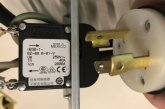
The 30A UPS input is to match the 30A twist-lock plug. However I just noticed the UPS breaker is rated 40A. Go figure...
plug.jpg

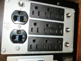
The 20A UPS output is to match the two 20A appliance cords that back-feed the panel. I have powered the house multiple times from the two 20A cords, switching off all non-critical breakers. The UPS has four receptacle sets, three at 15A and one at 20A.
outlet.jpg

Would be awesome to use the UPS internal transfer switch and not have to mess with the breaker interlock. Plus have the UPS float charge the batteries.
 
Last edited:
The 30A UPS input is to match the 30A twist-lock plug. However I just noticed the UPS breaker is rated 40A. Go figure...
Makes sense to me. The 30 Amp breaker is to protect the wire. The 40 Amp breaker is to protect the internal circuits of the UPS.
 
Makes sense to me. The 30 Amp breaker is to protect the wire. The 40 Amp breaker is to protect the internal circuits of the UPS.
In hindsight the 40A breaker makes sense to me too. The low-frequency inverter with two huge transformers has a massive surge capacity. Could remove the 30A power cord and hardwire to the panel with 8awg cable However I will never load the UPS that much.
 
Last edited:
If I did go this route I would buy a standard subpanel and use the automatic transfer switch from the UPS. Will transfer within a ¼ cycle without me having to get up from the couch. Also automatically transfer if I’m out of town with the wife at home. Plus float charge the batteries.

Will have to remove drywall from at least one side of the existing panel and pull the cables to the new subpanel.

I have an automatic transfer switch. The manual transfer switch is what I use to manage individual circuits. My autotransfer switches between grid/solar/generator. Since I normally get all my power from solar my autotransfer switches to grid if the batteries get low or to generator if the grid is down. There is actually nothing about the manual transfer switch that precludes you from automatically switching however you want. The manual transfer switch is surface mount or flush mount with a kit. I flush mounted so I did have to cut out some drywall. Minor surgery at most and much better appearance-wise. But yeah... anything you do besides cutting bus bars is a better idea.
 
If I did go this route I would buy a standard subpanel and use the automatic transfer switch from the UPS. Will transfer within a ¼ cycle without me having to get up from the couch. Also automatically transfer if I’m out of town with the wife at home. Plus float charge the batteries.

Will have to remove drywall from at least one side of the existing panel and pull the cables to the new subpanel.
Two important design considerations are not having to get up from the couch during a power outage and having a high wife acceptance factor. ;)

I was able to minimize drywall repair by surface mounting the sub panel an using wiring gutters. Invariably there will be some wires that aren't long enough to give enough working loop in a new panel and you can do splices in wiring gutters but not in sub panels.
 
... you can do splices in wiring gutters but not in sub panels.

Are you sure?

Under the heading "Danger Zone!", the question would be "why not? It works and is perfectly safe."

As for code, here are a couple links discussing it:


I use a lot of twin breakers like this one in 12 position 24 circuit panels:


Unlike full-size breakers, these don't have spaces for two wires (one on each side of the screw.) Not supposed to put two wires into one terminal, and with Romex sold conductor a ferrule to join two doesn't seem good either. So I splice two circuits to a short piece of wire using a wire nut. (Lately I've started using setscrew connectors instead of twist-on wire nuts. That solves the problem of not being allowed to put more than one wire in a screw terminal ... by putting three wires in a screw terminal ??)

 
you can do splices in wiring gutters but not in sub panels
Are you sure?
It always depends on your local jurisdiction. I was told by a reliable source and have followed that advice since then. It does make the panel look neater and that always helps with inspection.
YMMV.

Ampster stated "sub-panel". Typically not accepted in sub-panel but ok in main panel or gutter.
 
Ampster stated "sub-panel". Typically not accepted in sub-panel but ok in main panel or gutter.
Good to know. I did notice a splice in my main panel that the solar installers did after they replaced the main panel months after the solar install. They did not use wire nuts but NSI type connectors.
 
In my area, pigtails and junctions are allowed inside ANY approved switchgear.
Approved is key, and cubic inch box fill rules apply.
 
Humor me on this one. The intent is how to isolate critical/grid-down circuits in an existing breaker panel without major surgery to the wall, and safely isolate backup-power from grid power. And be reversible should I ever sell the house.

I have a 3000VA UPS being used as a grid-down inverter that back-feeds the panel. The UPS has an integral transfer switch and float charger that are currently not being used. I have a golf cart with 48V mobile battery set, and planning to purchase a 2nd 48V stationary battery set.

My existing breaker panel is only around 50% capacity. How dangerous would it be to cut the existing bus bars midway-panel and move any critical circuits (fridge, lights, master bedroom plugs) to the lower part of the panel? Then critical circuits would be constantly powered through the UPS, and safer than my manually sequencing the breakers. Please reference the following sketch.

View attachment 14888

During grid-down would allow me to have one battery set inside powering the house, and one set outside charging from the panels. Can also lift the UPS onto the cart and drive to a nearby family home and briefly power their fridge.
Watch for multiwire branch circuits, you would be powering both legs from one phase and potentially overload the neutral
 
Ampster stated "sub-panel". Typically not accepted in sub-panel but ok in main panel or gutter.
In my area, pigtails and junctions are allowed inside ANY approved switchgear.
Approved is key, and cubic inch box fill rules apply.

I went back and looked at the inspection notice on my situation - Small subpanel -no gutter. Circuits maxed out. Inspector didn't like splice in subpanel, but his detailed notes specified it was a box fill violation.
 

diy solar

diy solar
Back
Top