diy solar

diy solar

An Outback Skybox revival story

Yes, I've run a 1400w hair dryer on both L1 and L2. No 240v yet.

This did expose a possible problem with my batteries, which are new Weize 12v 100a LifePo batts. The voltage drop for the 1400w load is massive, and I'm seeing that even when measured at the battery terminals.

I'm discharging the batts at 800w now and plan to initiate a new charge that leaves them in Absorb stage starting at 55v (13.75v each) for an hour, or 2 Amps tail current (whichever comes first). I'm thinking the internal balance of the batteries is off, the most they've had under Absorb stage is 10 minutes.

I hope there's not a problem with the rate of discharge on these batteries. I didn't think 30-35 amps was too much to ask.
 
Batteries fully charged and rested. Showing 53.6v. Turn on hair dryer on high mode, battery discharge is showing 1.5-1.6kw. Battery voltage drops rapidly and is at 51.6 when I shut it off less than a minute after I started. Batteries recover right away and resting voltage returns to 53ish.

I do have too small a wire gauge on the batteries at the moment (8 total feet of #10), so I'd allow half a volt for that, but where is the other 1.5v? I'm measuring the voltage with a multi-meter at the batteries (individually as well) and they agree with what the Skybox is showing. Seems like the batteries just can't keep the voltage up under this load.
 
The manual that came with the batteries has me thinking this might be normal operation. The voltage drop is temporary under load, and not an indication of unavailable power. I'll have to try running something for a while to see what the batteries drop to after a much longer run time. I did switch to 4 gauge wire, but that didn't make any difference.
 
Now, back to the main event...

AFCI - theory of operation:

The AFCI connector has 4 pins. From left to right they are Power, Ground, Input, and Test.

When the Skybox is powered up, 13.8v is made available on Pin1. When the Sensata device is present, it powers on using this voltage and in turn grounds Pin3 to Pin2. The Skybox is expecting to see that pin 3 is grounded. That lets it know the AFCI device is in place.

The Skybox will conduct separate tests of the AFCI device. It does this when solar power is first made available, and when the AFCI test is selected from the Solar tile. It may do this at other times as well, maybe during sweeps, etc. I'm not sure. To conduct a test, the Skybox sends a brief millivolt level voltage pulse out Pin 4. The AFCI device sees this pulse and disconnects pin 3 from pin 2.

When the Skybox sees that Pin 3 is no longer grounded, it momentarily cuts off the voltage going to Pin 1. This is supposed to reset the AFCI device, which will cause Pin 3 to be reconnected to Pin 2.

I have noticed that the test option on the Solar tile only checks for the Pin 3 disconnect and reconnect. It doesn't seem to be concerned with the voltage reset. However, clearing an AFCI error, or engaging the solar power definitely does do this power reset check. If the timing of the test signal, followed by the pin2/3 disconnect, followed by the voltage reset, followed by the pin 2/3 reconnect is not done quickly but still with enough time for the Skybox to notice each of the changes, then a Critical Error will display.

AFCI bypass device:

To control the timing of the steps, I used an Arduino Uno clone. The Arduino checks voltage levels at the different pins, and controls the output to Pin 3 accordingly. Some minor electronics are needed outside the Arduino for that.

On Pin 1 I added a 12v regulator with a 1uF capacitor on the load side. This is to power the Arduino. The capacitor acts as a small buffer to keep the voltage steady for the Arduino when the Skybox drops the power on Pin 1 for a reset.

Pin 2 was easy. It's a ground. Nothing else is needed here.

Pin 3 gets connected to an NPN transistor, which acts as a switch to ground for Pin 3. The emitter of the transistor is connected to ground, the collector goes to Pin 3, and the base of the transistor is connected to the Arduino through a resistor. The resistor controls the base current. The resistor and transistor combination I used is drawing about 8 milliamps.

Pin 4 goes to an Op Amp. This is where I had the most trouble. Bringing 10-15 millivolts up into the 3-5 volt range is difficult to do without introducing a lot of noise when there is no signal from the Skybox. I originally had planned to use a really nice low noise op amp, but when it arrived I discovered it was smaller than a tick. Too small for me to work with. So, I used a standard 8 pin DIP OpAmp that I had on hand. This may be part of the noise problem, or not, but it led me to approach this an entirely different way. I've now setup the OpAmp to put out about 4.6v when there is no signal from pin 4. The Arduino watches this voltage and triggers when the voltage drops. Just the reverse of how I originally planned it. When the Skybox sends its test signal, the OpAmp comes down from it's rail voltage and only outputs the amplified test signal. This is probably only a volt or so. Perfect for the Arduino to trigger off of. To keep this low signal clean, I added an inductor and a capacitor to help filter any higher frequencies that may have been amplified. The goal being lower power going to the Arduino.
 
The software in the Arduino is pretty simple now. I had originally started with more complicated loops, where one condition depended on another, but I realized that was unnecessary when I had timing troubles. I also discovered that it's possible the Skybox is sometimes sending a voltage reset without starting with a test pin signal. So, instead of messing with logic, each of the 3 major events (Test, reset begin, reset return) can happen independently, and that can be controlled by simply watching the voltages supplied to the Arduino.

Here's the full code:

int TestInputPin = A4; // This sets the Test input from Skybox AFCI pin 4 to analog pin A4
int OutputPin = 3; // This sets digital pin 3 as the Output pin to Skybox AFCI pin 3
int VoltagePin = A1; // This sets the Power input from Skybox AFCI Pin 1 to analog pin A1

// Set integer variables to 0
int Testval = 0;
int PwrVal = 0;

void setup() {
// Default is AFCI engaged (Pin3 grounded)
analogWrite(3, 255); // Set digital output to 5v. This makes the open-collector transistor on OutputPin 3 connect AFCI Pin3 to ground
}

void loop() {
// Check for Test signal
Testval=analogRead(TestInputPin);
if (Testval < 600){ // Op-Amp inverted pulse from Pin 4 received
analogWrite(3, 0); // Set digital output to 0v. This makes open-collector transistor on OutputPin 3 release the AFCI Pin3 connection to ground
delay(20); // Make sure the skybox sees this open condition
} // Test completed

// Check for reset
PwrVal = analogRead(VoltagePin);
if (PwrVal <= 816) { // Reset(low voltage) detected
analogWrite(3, 0); // Set digital output to 0v. This makes open-collector transistor on OutputPin 3 release the AFCI Pin3 connection to ground
delay(20); // Make sure the skybox sees this open connection
} // Reset completed

// Check for repower
PwrVal = analogRead(VoltagePin);
if (PwrVal >= 850) { // Power(higher voltage) detected
analogWrite(3, 255); // Set digital output to 5v. This makes open-collector transistor on OutputPin 3 reconnect the AFCI Pin3 connection to ground
} // Repower completed
}

On the Arduino, I am only using Analog Pins 1 and 4, and Digital Pin 3 for the signals to/from the Skybox. Power is fed into the Arduino through the barrel connector, and the 5v generated by the Arduino is used to power the Op Amp.

The Analog pins are connected to a DAC on the Arduino board, which converts the voltage into a number. 0V = 0, and 5v = 1024, with each step being 4.9mv. That makes my trigger points of 600, 816, and 850 equal to 2.94v, 4v, and 4.17v respectively. These voltages were not calculated. They're actually the starting points I used for testing, and I never had to change them.

The digital pin which is used as an output is a PWM output. The Arduino allows you to send a high or low pulse at a frequency of your choice. By going as fast as it will allow (value 255), it has the effect of sending a constant 5v to the transistor's base to keep AFCI Pin 3 grounded.

I'm still working on the Schematic. I'll post that soon.
 
Last edited:
Question: Does PMB AFCI test have to pass before the skybox will start inverting? I don't have my BOS plugged in and I was able to power a skybox using a bench supply but it was not outputting 240V. It always wants me to clear the AFCI fault first. I guess there is no way to tell the box I have no solar plugged in?
 
That's correct. Once it notices the AFCI device is not there, it locks out the inverter. I don't know of a way to tell it that Solar is not used and the AFCI error can be ignored.
 
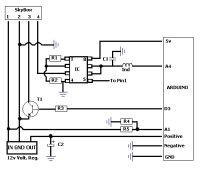
Here's the schematic for the AFCIB (B for bypass). I had originally built it with a 2SC4367 transistor because that's what I had on hand. I recently found out how unnecessarily expensive that older transistor is, so I replaced it with a more common transistor. I've only been running it for a week with the new one, but it seems to be working fine. Honestly, I didn't expect there to be any difference.

I used the schematic below to build a soldered version of the circuit, without referencing my prototype. This was to prove the schematic is good. I'm happy to report the finished version is running fine and has been since this morning. If there are any problems I'll let you know - but I don't expect any.

AFCIB schematic v.1.jpg
The Skybox numbered pins above are the AFCI connector on the unit itself. Referenced as 1 through 4, from left to right.

This is the parts list. I used 5% resistors.
R1 100k
R2 1k
R3 440 ohm (I used two 220ohm in series)
R4 3.3k
R5 5.6k + 820 ohm in series
C1 100nf ceramic
C2 1uf 50v electrolytic
Ind: 10uH (4x6mm)
Volt reg: LM340T12 (Any similar 12v regulator should do - just keep the output voltage under 12v. This one does 11.85v with the Arduino load)
OpAmp IC: AS358P-E1
Transistor: 2N2222A
Arduino: I used the Elegoo "super starter kit" on Amazon. It provides an Arduino clone, the "shield" you can build your circuit on, the 2N transistor, and a bunch of resistors that might match some of the above (I did not use them).

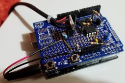
This is what it looks like assembled and ready to be plugged in:
Completed AFCIB v1.jpg
 
Last edited:
Hey Sollap
Is the Skybox still working?
What is the value of the inductor you used?
Thanks
 
Yes, the Skybox is still working. The AFCI bypass has been flawless.
The inductor is 10uH. I updated the parts list above. Thanks for pointing that out.
 
Yes, the Skybox is still working. The AFCI bypass has been flawless.
The inductor is 10uH. I updated the parts list above. Thanks for pointing that out.
Thanks so much for this. I just got a skybox also missing the BOS. I'm running AC coupled but didn't know the whole things will not run with the arc fault. Saves me a whole lot of time hooking my scope and logic analyzer to the thing.
 
I'm glad it's helpful. The one in my Skybox is still running fine without any issues.
 
If anyone else runs into the burned out "inductor" on that smaller circuit board I showed in Post #7, it's not actually an inductor. The 191 value is a part number for a Bourns line filter. SRF0504-191Y is the correct part.
 
I'm glad it's helpful. The one in my Skybox is still running fine without any issues.
Just a note. You're using a 12V regulator for the power supply but the voltage from the AFCI is 5V (at least it is on mine). Other than a filter cap the regulator shouldn't be necessary
 
The voltage between pins 1 and 2 on my skybox was showing 13.8vdc. I'm surprised you're only seeing 5vdc. I thought the original AFCI device was a 12v design.
 
The voltage between pins 1 and 2 on my skybox was showing 13.8vdc. I'm surprised you're only seeing 5vdc. I thought the original AFCI device was a 12v design.
actually, i went back and checked and its 3 Volts between pin 1 and ground. If I run the test it does jump up to about 7 volts I'm guessing pin 2 is a pulled down input somewhere and not true ground. only other thing I can think is I have the pins backwards. looking directly at the connector its 1234 left to right yes?
 
Yup, that's correct. From left to right. I just went and checked my box with the AFCIB unplugged, and my box shows 14.09vdc on those pins at startup.
 
Yup, that's correct. From left to right. I just went and checked my box with the AFCIB unplugged, and my box shows 14.09vdc on those pins at startup.
I only have the batteries connected, maybe need the grid connected too?
 
Back
Top