diy solar

diy solar

Seplos BMS goes bananas when NEEY is working!

So wait.. you spliced the cables ?

Battery terminal > crush ring > busbar > ring connector from PCB > (ring need BMS) > curated nut .. is what I used a few times before I drilled extra holes in busbar and never had any issues with that, although for safety the torque on all nuts is checked every year , and changed to drilled hole.

You do realize this BMS calculates resistance to cells amongst other things on every pcd connection I hope ?
Would surprise me at all the splicing causes issues with that process
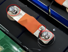
Have a look at the pictures i have attached, BMS/balancer cable is on a separate connection on the busbar, not connected at the terminals.
Both BMS and balancer shares PCB and cable to each busbar.
1702847498189.png
 
Have a look at the pictures i have attached, BMS/balancer cable is on a separate connection on the busbar, not connected at the terminals.
Both BMS and balancer shares PCB and cable to each busbar.

View attachment 183549

I know. Per the below, I was showing you...

EDIT: three places to attach a separate NEEY harness per bus bar:

This was tied back to your claim that you can't make modifications. You could simply detach the NEEY harness from the PCB and wire directly to any of these three locations on each bus bar.
 
I know this all ready, a couple of posts up i stated that i had ordered new cable leads for the NEEY balancer and will run them separetly from the PCB/BMS.
Even though i managed to top balance the pack with just 1A.
 
My issue is probably not a connection issue, but that the BMS and balancer are sharing thin cables. So when i discharge (or charge) a cell, the BMS sees a voltage drop (or spike). This was causing the BMS to throw warnings and alarms all over and ultimatly shutting it down.
This is a connection issue but not exactly in the way you're thinking.
But it sounds like you're on to it so all is well.
 
Lowering the equ-current to 1A did the trick quite nice.
I have however ordered extra cable leads, so i weill be using the full power of the balancer shortly.

View attachment 183536

When you had it at 4 amps I saw your screenshot showing 1 cell in the 4+ volts. Is this how the NEEY balancer works over volts the cell to push amps?
 
When you had it at 4 amps I saw your screenshot showing 1 cell in the 4+ volts. Is this how the NEEY balancer works over volts the cell to push amps?
No, it's just that when that "big" current flows through that "tiny" cable (from PCB to busbar, or perhaps including the PCB) it results in voltage misreading from the BMS.
Actual voltage on the terminals for that cell was ok (measured with multimeter). Also the Enerkey app (for managing the balancer) showed the correct measurements.

So buy extra balancer leads and don't use the PCB for the balancer, use it only for BMS.
 
Do you have a way to measure the voltage coming off of the balancer? I don't think your BMS was acting weird I think it was detecting the voltage from the NEEY balancer. I think the reason NEEY is able to constantly balance at a set amp rate is because it over volts the cell.

I saw something very similar when charging cells with the ZKE 40, towards the end it slow down, but if you don't wait you can set the voltage to like 4.2 volts and all of a sudden instead of sending .4 amps it will shoot up to 3-4 amps. So it would speed up the charging but you were also sending incoming voltage to the cell above 3.65 so maybe it could be hurting the cell?
 
I know this all ready, a couple of posts up i stated that i had ordered new cable leads for the NEEY balancer and will run them separetly from the PCB/BMS.
Even though i managed to top balance the pack with just 1A.
Just for future reference both the Neey active balancer and JK bms’s are very adaptable to various lead lengths. You can splice to extend or cut it to a stub, they will calculate the resistance and adapt. You don’t need to keep them the same length, just long enough to be neat and not too taught. Im sure as you now know they don’t share well. The Neey cranks current down the little wire, pauses, evaluates the result and decides on the next cell to fill or drain. The Neey is even blinded during the process. You can only imagine what the bms was thinking. IMG_1174.jpeg
 
Do you have a way to measure the voltage coming off of the balancer? I don't think your BMS was acting weird I think it was detecting the voltage from the NEEY balancer. I think the reason NEEY is able to constantly balance at a set amp rate is because it over volts the cell.

Never. It may give a high voltage reading at the NEEY end of the harness, but the cell will not measure over volt at the terminals.

The NEEY measures how its activity affects the voltage measurement and compensates.
 
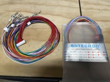
I have came across the same problem. Using the eel kit. If I remove the neey harness cables from PCB and connect my other set of cables to the same small hole that the BMS uses it should be fine or does it need to be connected to the positive terminal stud.
 
I have came across the same problem. Using the eel kit. If I remove the neey harness cables from PCB and connect my other set of cables to the same small hole that the BMS uses it should be fine or does it need to be connected to the positive terminal stud.
You should be able to use the same smaller hole in the busbar (that connects to the PCB aswell). That is what i intend to do once my cables is delivered.
 
Will get that down before I head to bed as I'm trying to discharge my pack to see what it will charge up to during cheap rate.
 
I had one dead cell that I had to replace was going for the option not to top balance and am not to sure where my pack is roughly among other cells. Neey should bring new cell to same as others
 
I had one dead cell that I had to replace was going for the option not to top balance and am not to sure where my pack is roughly among other cells. Neey should bring new cell to same as others
But that is when using an active balancer, and yes it will do so..

Again, these PCB leads are only ment for the seplos BMS, as the BMS calculates quite a lot of parameters .
Next to that, the traces are too small to do anymore current than max 1a as @MrSwede already noticed..

This is , by all means, and as already stated a user/install error.

If using a neey, use it's own leads , perf. Using their own busbar connection and you'll be a happy camper
 
Last edited:
Can someone measure the voltages coming off the neey balancer see if they are in the 4 volt range (using the 4 amp setting or even 3)

Please...

With cherry on top...

Unless your diabetic in that case a sugar free candy drop...

Thanks ?
 
Changed the cables I have several different versions of cables. I have 1 for PCB board connection I have another for terminal connections and the last cable is to add to small screw hole. Using the terminal connection cable. Hopefully set can balance by morning have neey back to 4 amps again.
 
if this causes such problems why has EEL adapted the PCB board to fit the Neey on to it. At present have been charging for some time and the voltage difference is dropping slowly currently at 0.052v. had the battery charging at 10 amps not sure why it was set so low so gonna miss the cheaper charge window for tonight.
 
if this causes such problems why has EEL adapted the PCB board to fit the Neey on to it. At present have been charging for some time and the voltage difference is dropping slowly currently at 0.052v. had the battery charging at 10 amps not sure why it was set so low so gonna miss the cheaper charge window for tonight.
Because EEL in reality is a copy cat, and sales organisation and not a engineering company.
May I suggest you read the BMS manual ( it is posted in the resource section), if you do so, you'll find out pretty quick why the BMS limited the charge amps
 
Back
Top