diy solar

diy solar

Mystery used Sol-Ark 12K Full Failure (Fixed itself)

I believe I tried that, I think it still turned on the screen but kept the Inverter board off. Which is weird since it means it is capable of pulling power from battery atleast enough to power itself. I think even PV only had the screen working but staying off otherwise
Battery powering screen is ok (low voltage). Pv powering screen means the connection from high voltage to low voltage is working. Maybe the high voltage bus to inverter is faulting. Lots of capacitors there, so not diy friendly repair.
 
That seems pretty poor. That's like being able to roll back the odometer of your car before selling it?? Lol
Lol has anyone actually gotten the password on these forums? I didn't try but it could be 0000 for all I know.
 
Battery powering screen is ok (low voltage). Pv powering screen means the connection from high voltage to low voltage is working. Maybe the high voltage bus to inverter is faulting. Lots of capacitors there, so not diy friendly repair.
Capacitors usually blow correct? Blown capacitors in my experience emit alot of smoke and residue and will smell bad in the box forever basically lol. Neither was detected inside this unit from basic opening of panel. Is there some other way the DC bus could fail less noticeable from over voltage? Also not so DIY, working with capacitors is fairly common for me.
 
A common mistake with the error codes you stated is someone accidentally connected an AC input source to AC output of inverter.

Easy to do if you put manual AC breakers from main panel to auxiliary panel to provide backup bypass for inverter.
 
Like grid input wires into load output? It's possible... any idea what exactly gets damaged?
A common mistake with the error codes you stated is someone accidentally connected an AC input source to AC output of inverter.
 
Like grid input wires into load output? It's possible... any idea what exactly gets damaged?
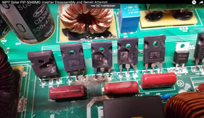
Usually the AC PWM IGBT H-bridge devices. They often take out the gate drivers also. If they short out, they can also blow out the battery side MOSFET's.

On SolArk's, these devices are buried below several layers of PCB boards on back heat sink requiring removing a couple hundred little screws.

This is picture of a MPP HF inverter that had AC input source hooked up to inverter AC output.

HF inverter with blown PWM IGBT's.jpg
 
Usually the AC PWM IGBT H-bridge devices. They often take out the gate drivers also. If they short out, they can also blow out the battery side MOSFET's.

On SolArk's, these devices are buried below several layers of PCB boards on back heat sink requiring removing a couple hundred little screws.

This is picture of a MPP HF inverter that had AC input source hooked up to inverter AC output.

View attachment 185407
This is exactly the kind of info I was hoping for, Thank you!. Have people had luck finding replacement components and soldering new ones in?
 
Don't laugh, is the on/off switch connected ?
Mine was reversed, the on/off part worked but not the light because its an LED.
 
Interesting, I checked most connectors but didn't closely examine the switch since it did glow blue when pushed.
Don't laugh, is the on/off switch connected ?
Mine was reversed, the on/off part worked but not the light because its an LED.
 
Usually the AC PWM IGBT H-bridge devices. They often take out the gate drivers also. If they short out, they can also blow out the battery side MOSFET's.

On SolArk's, these devices are buried below several layers of PCB boards on back heat sink requiring removing a couple hundred little screws.

Does this kind of “hundred of screws removed” mean that these inverters are not designed for easy servicing for some failures? What failures are easy to do a board swap for?

Also doesn’t a hybrid have to tolerate parallel output from PWM from grid? Or is the issue that it expects the grid to be isolated until qualify and sync is done, vs AC just rudely showing up without the protection of the transfer relay.
 
Usually the AC PWM IGBT H-bridge devices.
Wouldn't they just freewheel and passively rectify incoming AC into DC and charge DC bus capacitors? The IGBT body diodes in inverter H-bridge look like they form a bridge rectifier.
 
Usually the AC PWM IGBT H-bridge devices. They often take out the gate drivers also. If they short out, they can also blow out the battery side MOSFET's.

On SolArk's, these devices are buried below several layers of PCB boards on back heat sink requiring removing a couple hundred little screws.

This is picture of a MPP HF inverter that had AC input source hooked up to inverter AC output.

View attachment 185407
I don't think the battery input is shorted, the battery seemed to handle being hooked up okay, granted I didn't check for dead short and I should have but it read like 53V on the screen so I doubt it's shorted
 
Ah ok. Well if you wired the AC onto the wrong end I’m not sure the inverter can be blamed for not detecting the AC and refusing to start.
The inverter has to be active, independently putting AC output with battery power that is out of sync with applied AC on output terminals to blow the H-bridge IGBT's.
 
Also worth noting, in that video the Inverter shown is not backfeed capable, though I'm not sure if that means solark can handle a reverse connection like that better or not.
The inverter has to be active, independently putting AC output with battery power that is out of sync with applied AC on output terminals to blow the H-bridge IGBT's.
 
Capacitors usually blow correct? Blown capacitors in my experience emit alot of smoke and residue and will smell bad in the box forever basically lol. Neither was detected inside this unit from basic opening of panel. Is there some other way the DC bus could fail less noticeable from over voltage? Also not so DIY, working with capacitors is fairly common for me.
My point is that you may have large energized capacitors that need to be discharged before working on the board. Not that they have blown.
 
My point is that you may have large energized capacitors that need to be discharged before working on the board. Not that they have blown.
Gotcha, yeah that's something I can handle assuming I could find the issue and it seemed fixable
 
The inverter has to be active, independently putting AC output with battery power that is out of sync with applied AC on output terminals to blow the H-bridge IGBT's.
Wait so that's quite different than just reversing the wires and turning on?
 
What do you mean by reverse? Wire to AC out instead of AC in?
I'm not sure I'm just trying to get to the bottom of that the other person is talking about as far as this potential failure to judge how likely it is to be related to my issue based on the difference in Inverter architecture and likelihood of someone doing it on accident. For example if he means feeding the load side with grid once everything is already on and working correctly then that seems unlikely to be done on accident but if he means just simply reversing grid and load during installation and then turning on can cause this then its more likely which then tells me to dig deeper for damaged fets or igbts
 
I'm not sure I'm just trying to get to the bottom of that the other person is talking about as far as this potential failure to judge how likely it is to be related to my issue based on the difference in Inverter architecture and likelihood of someone doing it on accident. For example if he means feeding the load side with grid once everything is already on and working correctly then that seems unlikely to be done on accident but if he means just simply reversing grid and load during installation and then turning on can cause this then its more likely which then tells me to dig deeper for damaged fets or igbts

I was reading this thread as reversing grid and load initial installation. Seems quite plausible.
 

diy solar

diy solar
Back
Top