diy solar

diy solar

Valence XP Super Thread

I can tell you've paid good attention to the details and you are correct to assume that there's no need to worry. I repeat there's no need to worry about the 50MV difference.

One thing to remember about the 14.6 volt charger is that if you are charging a battery thats severely out of balance it will overpower the bleed off resistor and drive one cell over-voltage so if You're balancing a battery for the first time you should pay close attention and probably use the lower voltage charger for that purpose. Any cell above 3.43 is pretty much full and the same state of charge as a cell that's at 3.8. if in doubt just look at the state of charge meter it will not jump to 100% until it is truly balanced.

Thanks Travis! This does ease my mind. To think I was going to grab a bench charger to pull that cell up those few mv. I think your reply will keep my OCD at Bay.

Only other thing I've noticed that I haven't seen here on the forums:

Most batteries I have keep communication, some show the pink communication lost, and a few show the pink comm lost with a periodical flash of their firmware date and version. The last being one I've never seen mentioned here, has anyone experienced this?

None of these anomalies appear to impede charging or use thus far.

Thanks

The only time I've had periodic flashes is when I had a lot of batteries connected without the terminating resistor. now I don't know what flash you mean like it periodically appears or it periodically disappears for a short time. In my case most of the time all the information updated rapidly and was viewable and sometimes dropped out for a moment.

Remember the balancing boards on the batteries will continue to balance for quite a while after you disconnect the communication cable so even if communication drops momentarily the balancing is still working. I think it continues for 5 minutes. you can tell because the light flashes every 5 seconds for about 5 minutes after you disconnect the cables and you can feel the resistors are still warm but after the flashing changes to every 20 seconds the resistors no longer get warm.

however there's probably a different margin of error when the batteries are in communication with the BMS. what I'm worried is if you have too many communication errors the BMS might disconnect the battery Bank. So far my BMS has never disconnected the battery Bank for any reason.

But one thing I have noticed is the BMS will balance if the BMS was turned on regardless of whether it disconnected the contactor or not.

What I mean is I had a BMS configured for 24 batteries in series. I connected it to 2 batteries in series and then powered up the BMS. The BMS connected its battery contactor for about 10 seconds and then it decided that some of the batteries were missing so it disconnected the battery contactor / relay. But it continued to balance indefinitely. Module 2 module and cell block to cell block balancing was working. I think if I had connected a battery number 25 which is outside of the 1 through 24 it would not have been the exact same results but I'm over-analyzing already so I'll stop here.

Hmm interesting thought on continuous errors causing possible bms disconnect of the bank. I only have 3 that have this problem of 20. You're right, I have seen it once or twice on some batteries over long term connections which doesn't seem to be a concern. Three do it continuously every 2 seconds or so
The only time I've had periodic flashes is when I had a lot of batteries connected without the terminating resistor. now I don't know what flash you mean like it periodically appears or it periodically disappears for a short time. In my case most of the time all the information updated rapidly and was viewable and sometimes dropped out for a moment.

Remember the balancing boards on the batteries will continue to balance for quite a while after you disconnect the communication cable so even if communication drops momentarily the balancing is still working. I think it continues for 5 minutes. you can tell because the light flashes every 5 seconds for about 5 minutes after you disconnect the cables and you can feel the resistors are still warm but after the flashing changes to every 20 seconds the resistors no longer get warm.

however there's probably a different margin of error when the batteries are in communication with the BMS. what I'm worried is if you have too many communication errors the BMS might disconnect the battery Bank. So far my BMS has never disconnected the battery Bank for any reason.

But one thing I have noticed is the BMS will balance if the BMS was turned on regardless of whether it disconnected the contactor or not.

What I mean is I had a BMS configured for 24 batteries in series. I connected it to 2 batteries in series and then powered up the BMS. The BMS connected its battery contactor for about 10 seconds and then it decided that some of the batteries were missing so it disconnected the battery contactor / relay. But it continued to balance indefinitely. Module 2 module and cell block to cell block balancing was working. I think if I had connected a battery number 25 which is outside of the 1 through 24 it would not have been the exact same results but I'm over-analyzing already so I'll stop here.


All really great points and some great information.

To provide a little more context; I have 20 batteries and 3 that always show the communication error in pink and flash only the two fields "F/W Rev" and "F/W Date" off every 3 seconds (only disappearing for a split second). Even while flashing they continue to provide data. This same thing happens while reading through the chain or only the single battery connected.

Either way, I bought 10 valence battery boards as cheap insurance. Hopefully they'll stay in the closet.
 
Off topic: I decompiled the 1212 exe and noticed that it has 7 methods for balencing. One for all cells and then one for each cell 1-6. Seems like it takes simple Boolean values for on/off. If I get some time I may convert the decompile into a visual studio project and add some buttons to manually control these.

Has anyone tried or played with a decompiled version of the software?
There's a four or was it 5 tab version that has a manual balancing tab but it doesn't seem to work for me or any of the few people I know who have tried it.
 
I have not but please share if you are able to deconstruct.
There's a four or was it 5 tab version that has a manual balancing tab but it doesn't seem to work for me or any of the few people I know who have tried it.

Yeah..... So I pulled a late night scraping through the code last night and read through almost all of the code.

It may already be known here, but first thing I found that you can enable on the 1212 without modification gets you the calibration tab and the ability to change all of the preset values.

To enable this tab all you need to do is go into the install directory and open the moduledialogg2.config file and change the productionconfigurationoption = false.

The "Battery Control" tab still exists in the code and it looks like the logic to execute the function needed to trigger the communication is all in place. Only problem is, upon loading the main form they call for it to be removed. This is something that is not configurable from the configuration file, so I'll need to export it to a project to enable it. Export has been tricky, it's going to take a little while.

Last, I'm going to try and document all of the code functions and how they are triggered. Again this may take some time.
You know what would be the ultimate hack for the XP line? Actually reflashing a chip on the board that's inside the battery. Add some lines of code that as well as do its regular functions also Tell it to activate the 12 volt resistor anytime the battery reaches 14.4v and activate the cell block balancing protocol. that way these batteries will self balance themselves without needing to be hooked to an external communication device.

you know the more I think about this the more I think that somebody might be able to pull boards out of the RT line and install them into the XP battery in order to accomplish this.

Another thought we could extract the code from the RT chip and flash it into the XP board.


It would be great to get an rt board to compare the PCB. I have mixed feelings on it though....... I wonder what the board consumption is for the rt. I would guess they wouldn't be able to sleep the board since it's constantly monitoring the battery.
 
Here are all of the comm functions in the software:

Public Function BalanceReadReturn(ByVal Buffer As Object) As Boolean
Line 998: Public Function BalanceReadSend() As Byte()
Line 1008: Public Function BatteryBalanceReturn(ByVal Buffer As Object) As Boolean
Line 1025: Public Function BatteryBalanceSend(ByVal BalanceSelection As UShort) As Byte()
Line 1035: Public Function BatteryCycleRead() As Byte()
Line 1045: Public Function BatteryCycleReturn(ByVal Buffer As Object) As Boolean
Line 1064: Public Function BatteryMaximumRead() As Byte()
Line 1074: Public Function BatteryMaximumReturn(ByVal Buffer As Object) As Boolean
Line 1107: Public Function BatteryStatusRead() As Byte()
Line 1117: Public Function BatteryStatusReturn(ByVal buffer As Object) As Boolean
Line 1136: Public Function BatteryVersionRead() As Byte()
Line 1146: Public Function BatteryVersionReturn(ByVal Buffer As Object) As Boolean
Line 1189: Public Function BatteryWHRead() As Byte()
Line 1199: Public Function BatteryWHReturn(ByVal Buffer As Object) As Boolean
Line 1218: Public Function CalibrateTemp() As Byte()
Line 1228: Public Function CalibrateTemp(ByVal paramid As Integer) As Byte()
Line 1238: Public Function Calibraton0ARead() As Byte()
Line 1248: Public Function Calibraton0AReturn(ByVal Buffer As Object) As Boolean
Line 1261: Public Function Calibraton100ARead() As Byte()
Line 1271: Public Function Calibraton100AReturn(ByVal Buffer As Object) As Boolean
Line 1284: Public Function Calibraton10ARead() As Byte()
Line 1294: Public Function Calibraton10AReturn(ByVal Buffer As Object) As Boolean
Line 1307: Public Function CheckCalibrationMode() As Byte()
Line 1317: Public Function CheckmoduleRead() As Byte()
Line 1327: Public Function CheckmoduleReturn(ByVal Buffer As Object, ByVal productmodel As String) As Boolean
Line 1366: Public Function CloseCalibratonRead() As Byte()
Line 1376: Public Function CloseCalibratonReturn(ByVal Buffer As Object) As Boolean
Line 1389: Public Function CRC16(ByVal data As Byte(), ByVal datalen As Integer) As Byte()
Line 1418: Public Function current100ARead() As Byte()
Line 1428: Public Function current100AReturn(ByVal Buffer As Object) As Boolean
Line 1446: Public Function current10ARead() As Byte()
Line 1456: Public Function current10AReturn(ByVal Buffer As Object) As Boolean
Line 1475: Public Function EnterCalibrationMode() As Byte()
Line 1485: Public Function EnterCalibrationMode(ByVal paramid As Integer) As Byte()
Line 1495: Public Function EventLog2Read() As Byte()
Line 1505: Public Function EventLog2Return(ByVal Buffer As Object) As Boolean
Line 1529: Public Function EventLogRead() As Byte()
Line 1539: Public Function EventLogReturn(ByVal Buffer As Object) As Boolean
Line 1568: Public Function ExitCalibrationMode() As Byte()
Line 1578: Public Function ExitCalibrationMode(ByVal paramid As Integer) As Byte()
Line 1588: Public Function ModelReadReturn(ByVal Buffer As Object) As Boolean
Line 1636: Public Function ModelReadSend() As Byte()
Line 1646: Public Function OpenbalancingRead() As Byte()
Line 1656: Public Function OpenbalancingReturn(ByVal Buffer As Object) As Boolean
Line 1669: Public Function ReadCalibrationMode(ByVal Buffer As Object) As Boolean
Line 1691: Public Function SendTempData(ByVal Temp As Single) As Byte()
Line 1721: Public Function SendTempData(ByVal Temp As Single, ByVal paramid As Integer) As Byte()
Line 1751: Public Function SetID(ByVal NewID As String) As Byte()
Line 1763: Public Function SNSOCReadReturn(ByVal Buffer As Object) As Boolean
Line 1804: Public Function SNSOCReadSend() As Byte()
Line 1814: Public Function StartCalibratonRead() As Byte()
Line 1824: Public Function StartCalibratonReturn(ByVal Buffer As Object) As Boolean
Line 1837: Public Function StopbalancingRead() As Byte()
Line 1847: Public Function StopbalancingReturn(ByVal Buffer As Object) As Boolean
Line 1860: Public Function TempRead() As Byte()
Line 1870: Public Function TempReturn(ByVal Buffer As Object) As Boolean
Line 1929: Public Function Verify0AReturn(ByVal Buffer As Object) As Boolean
Line 1948: Public Function Verify150AReturn(ByVal Buffer As Object) As Boolean
Line 1967: Public Function Verify200AReturn(ByVal Buffer As Object) As Boolean
Line 1986: Public Function Verify20AReturn(ByVal Buffer As Object) As Boolean
Line 2005: Public Function Verify2AReturn(ByVal Buffer As Object) As Boolean
Line 2024: Public Function Verify3AReturn(ByVal Buffer As Object) As Boolean
Line 2043: Public Function Verify5AReturn(ByVal Buffer As Object) As Boolean
Line 2062: Public Function Verify8AReturn(ByVal Buffer As Object) As Boolean
Line 2081: Public Function VerifyRead() As Byte()
Line 2091: Public Function VerifySetID(ByVal Buffer As Object) As Boolean
Line 2109: Public Function VoltRead() As Byte()
Line 2119: Public Function VoltReturn(ByVal Buffer As Object) As Boolean
Line 2146: Public Function Wakeup() As Byte()
Line 2156: Public Function writetoflashRead() As Byte()
Line 2166: Public Function writetoflashReturn(ByVal Buffer As Object) As Boolean
 
I was able to convert to a project successfully, and two key strokes to enable the battery tab. It still however does not work; I'm getting communication errors when I try and run it. What I can guess is one of two things, either the board doesn't support external commands to balance or the feature is broken in the code. I tried setting up a few breakpoints last night to debug and got down to the 232 communication logic, I need to spend a little more time reviewing it.

Thanks.
 

Attachments

  • pic.png
    pic.png
    195.9 KB · Views: 54
I just saw these thread updates. I tried decompiling and doing the exact same thing like a month ago. I got to exactly the same point*, but couldn't actually get the balancing feature to work. It looked like there was a command through the 232 layer that it was supposed to send when you enable balancing, but it didn't seem to actually do anything. I think I had to do some mods to get it to send the right command, but it still didn't work. I traced it down through the layers, but I forget where I got to. I had moved on to other things, but I could take a look again. It seems like if we could enable intercell balancing and intracell balancing, some easy modifications could make this into a easy BMS (with like a relay to a contactor).

*Edit: I actually was able to enable the balancing button and have it try to send the RS232 command, but it wouldn't actually enable balancing.
 
Last edited:
I just saw these thread updates. I tried decompiling and doing the exact same thing like a month ago. I got to exactly the same point*, but couldn't actually get the balancing feature to work. It looked like there was a command through the 232 layer that it was supposed to send when you enable balancing, but it didn't seem to actually do anything. I think I had to do some mods to get it to send the right command, but it still didn't work. I traced it down through the layers, but I forget where I got to. I had moved on to other things, but I could take a look again. It seems like if we could enable intercell balancing and intracell balancing, some easy modifications could make this into a easy BMS (with like a relay to a contactor).

*Edit: I actually was able to enable the balancing button and have it try to send the RS232 command, but it wouldn't actually enable balancing.


I'm really starting to think that inter-battery balencing is completely controlled by the board itself and that it does not take external input on that matter (besides monitoring). However I think it's the BMS that controls the intra battery balencing. I haven't started playing with the BMS yet, it's the hv and have to run it for a 48v set. If we can capture the modbus command that triggers the intracell balencing we're good. We should be able to use a cheap modbus plc with a built-in webserver to do whatever we want.
 
Well, did some decompiling today and searching through the bms software. I think I figured out the proper usb can bus adapter that will work with the BMS. Another valence user and I placed an order for the adapter tonight and I should hopefully be able to verify in the next week or so.

Kevin
 
Well, did some decompiling today and searching through the bms software. I think I figured out the proper usb can bus adapter that will work with the BMS. Another valence user and I placed an order for the adapter tonight and I should hopefully be able to verify in the next week or so.

Kevin
I think that the external BMS sends the command to the internal board in order to balance the 12v module. so although you're getting errors trying to send commands to cause a Cell Block to balance I'm wondering if you see a different command for activating the 12 volt resistor?
 
I think that the external BMS sends the command to the internal board in order to balance the 12v module. so although you're getting errors trying to send commands to cause a Cell Block to balance I'm wondering if you see a different command for activating the 12 volt resistor?


This is all theory!!!!

How to enable cell balancing outside of the software:


The common Battery Monitoring 1212 software just monitors the Battery Board and can change the ID, nothing more. My theory is that you would need to have something that sends the wake modbus command to the Battery Board if you simply wanted to enable cell balancing and the cells were outside of the parameters hard coded into the battery board firmware (Seems like 50mv difference).

BMS Software Review:

I have not gotten the canbus connection yet so this is all in theory while i wait for my adapter to arrive.

What appears to be in the software:
-BMS flashing and configuration.
-CAN monitoring of the BMS, charts etc.
-Printer Drivers for Zebra.
-Possibility to manually trigger contactor.


Looking at the code for the BMS Monitoring Software, I do see that it has a checkbox for intra module balancing in the canbus class. This may or may not be controllable via the software, it appears as though it may be.

Other thoughts:

I'm 100% sure that the BMS can trigger the battery module balancing. I think it may be needed to either sniff the communication between the BMS and the battery or possibly getting a copy of the bms firmware to look into.


Kevin
 
Thanks @Travis for starting this thread and posting so much useful info. It's been enormously helpful. Hitting 'like' on your many posts would take forever, so please accept a blanket "like' and thanks.

I'm still pretty new to Li batteries and looking for a little guidance from the experts....

I purchased two U27-12XPs in 2018 before there was much info about them. One I've used as a home UPS, on float at 13.9v, and it's seen only a few charge cycles. With the diag s/w (thanks for the upload, it's super helpful), it shows all cells balanced to ~30 mv.

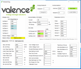
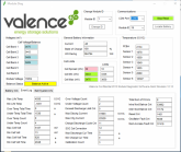
The second battery was in storage for the last year. I charged it with 14.1v @ 5 amps and monitored with diag s/w. The cells were initially balanced so I bumped the current to 10 A. Eventually one cell reached 13.7+ volts while others lagged behind around 3.3-3.4v. (first image below). Based on the user manual, I guess the U-BMS cycles the charge contactor off/on while keeping the highest cell between 13.75 and 13.8v, until the fine balancing brings the lower cells up. I manually cycled the charger on/off keeping the high cell under 3.8, but that got old really quick (now I see why a BMS with contactor control is so important). I removed the side cover and charged 3 low cells separately to 3.50-3.55v. Then continued charging with 13.85v @ 1 amp. Over the next 24 hours the battery has stayed in 'balance active' mode and is around 35 mv spread. (second image below). The lowest cell still seems less responsive than others to balancing and remains lower than others.

The event logs show high (> 5v) and low (13 mv) events. I'm wondering if this is enough to damage the battery? The event log of battery #1 is very similar to this one, though it doesn't have the high/low cell voltage events. Curious what others' experiences are...
 

Attachments

  • 2020-07-03_19_event-log.png
    2020-07-03_19_event-log.png
    250 KB · Views: 53
  • All-cells after 24 hours.png
    All-cells after 24 hours.png
    276.5 KB · Views: 52
Thanks @Travis for starting this thread and posting so much useful info. It's been enormously helpful. Hitting 'like' on your many posts would take forever, so please accept a blanket "like' and thanks.

I'm still pretty new to Li batteries and looking for a little guidance from the experts....

I purchased two U27-12XPs in 2018 before there was much info about them. One I've used as a home UPS, on float at 13.9v, and it's seen only a few charge cycles. With the diag s/w (thanks for the upload, it's super helpful), it shows all cells balanced to ~30 mv.

The second battery was in storage for the last year. I charged it with 14.1v @ 5 amps and monitored with diag s/w. The cells were initially balanced so I bumped the current to 10 A. Eventually one cell reached 13.7+ volts while others lagged behind around 3.3-3.4v. (first image below). Based on the user manual, I guess the U-BMS cycles the charge contactor off/on while keeping the highest cell between 13.75 and 13.8v, until the fine balancing brings the lower cells up. I manually cycled the charger on/off keeping the high cell under 3.8, but that got old really quick (now I see why a BMS with contactor control is so important). I removed the side cover and charged 3 low cells separately to 3.50-3.55v. Then continued charging with 13.85v @ 1 amp. Over the next 24 hours the battery has stayed in 'balance active' mode and is around 35 mv spread. (second image below). The lowest cell still seems less responsive than others to balancing and remains lower than others.

The event logs show high (> 5v) and low (13 mv) events. I'm wondering if this is enough to damage the battery? The event log of battery #1 is very similar to this one, though it doesn't have the high/low cell voltage events. Curious what others' experiences are...
you're welcome. Unfortunately I don't have any experience with running these batteries Under and over voltage to determine if and how much they get damaged. Your batteries don't have many cycles. I also noticed that the second counter for the time it's been Under and over voltage is low so they must not have spent very much time at those levels. I'm really curious for you to do a quality battery capacity test. . With that few of cycles I might expect it could hold over spec but with the Under and over voltage in the history who knows. The over-voltage could have happened once when you were charging because it sounds like those few cells that needed a boost would have drove the ones that reached full first way over 4 volts if you tried to go higher than 13.6. you mentioned they were having trouble getting over 3.4 which means they were definitely not full. I don't consider them full until they're consistently stable over 3.45 and in that case if there still charging they'll start to shoot up rapidly from there.
I've heard a few people running the voltage down under 1 volt per cell and claiming that their capacity was still fine but they didn't have any actual capacity test to back up their claim. It was just more or less them feeling like the batteries were still performing well.
 
Thanks @Travis for starting this thread and posting so much useful info. It's been enormously helpful. Hitting 'like' on your many posts would take forever, so please accept a blanket "like' and thanks.

I'm still pretty new to Li batteries and looking for a little guidance from the experts....

I purchased two U27-12XPs in 2018 before there was much info about them. One I've used as a home UPS, on float at 13.9v, and it's seen only a few charge cycles. With the diag s/w (thanks for the upload, it's super helpful), it shows all cells balanced to ~30 mv.

The second battery was in storage for the last year. I charged it with 14.1v @ 5 amps and monitored with diag s/w. The cells were initially balanced so I bumped the current to 10 A. Eventually one cell reached 13.7+ volts while others lagged behind around 3.3-3.4v. (first image below). Based on the user manual, I guess the U-BMS cycles the charge contactor off/on while keeping the highest cell between 13.75 and 13.8v, until the fine balancing brings the lower cells up. I manually cycled the charger on/off keeping the high cell under 3.8, but that got old really quick (now I see why a BMS with contactor control is so important). I removed the side cover and charged 3 low cells separately to 3.50-3.55v. Then continued charging with 13.85v @ 1 amp. Over the next 24 hours the battery has stayed in 'balance active' mode and is around 35 mv spread. (second image below). The lowest cell still seems less responsive than others to balancing and remains lower than others.

The event logs show high (> 5v) and low (13 mv) events. I'm wondering if this is enough to damage the battery? The event log of battery #1 is very similar to this one, though it doesn't have the high/low cell voltage events. Curious what others' experiences are...
How long did it take when you took the side cover off to get the lowest cell charged? At how many amps? What I'm getting at is how many amp hours behind was it?
 
Cell 2 - it went from 3.36v to 3.48v in about 17 hours. Current limited to 0.5 amps and I think was still charging around 0.2 amps when I stopped and moved to cell 3.
 
Back
Top