I took apart a microwave, because it's not in my nature to throw anything broken away without disassembling it and seeing how it works first. Don't worry, I have absolutely no intention of powering it up. I'm going to use the copper coils for another project instead.
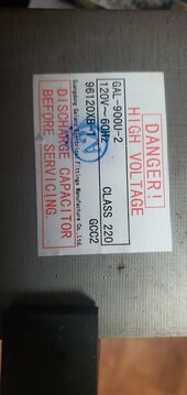
Here's the transformer specs.

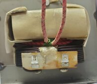
On one side of the transformer is the primary and secondary coil, they both have continuity between each of the leads, both the red wires on the top, and the two spade connectors on the bottom.

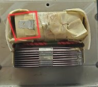
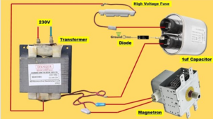
However, the other side of the transformer has a single spade connector, that does not have continuity with the casing, or either the primary or secondary coil, and I can't find another tap anywhere near it, and it has no continuity with any part of the transformer that I can find. Connected to that wire was a 5 kV, 0.3a glass fuse in a holder, and I didn't pay attention to what it came off of originally.

Any help in identifying and what that fifth wire is would be greatly appreciated.
Here's the transformer specs.

On one side of the transformer is the primary and secondary coil, they both have continuity between each of the leads, both the red wires on the top, and the two spade connectors on the bottom.

However, the other side of the transformer has a single spade connector, that does not have continuity with the casing, or either the primary or secondary coil, and I can't find another tap anywhere near it, and it has no continuity with any part of the transformer that I can find. Connected to that wire was a 5 kV, 0.3a glass fuse in a holder, and I didn't pay attention to what it came off of originally.

Any help in identifying and what that fifth wire is would be greatly appreciated.


