diy solar

diy solar

An Outback Skybox revival story

I don't recall if my box required the AFCI when on batteries only, but I tend to think that it does. It's a safety device for the PV, one they made the whole system dependant on, so my guess is that it would be activated either way.
There is a 12v relay in that area, and one of the outputs on that multiconnector is 12v. I wonder if it's the same power circuit. You could see what voltage is being output on the AUX 12v Power terminal. It it's the same 5v or so you are seeing on the AFCI pin then I think that says there is a power problem there. BTW, I don't think that 12v AUX output is always on. One of the settings for RSD output or something like that controls it. You'll need to find the right menu item to get it to go.
Connected the grid and no difference so it isn't that. I think the 12V aux settings are in the skybox pages. Which multi connector do you mean? The AFCI 4 pin or that black/orange phoenix connector? And one other thing what revision is you main board? Mine says Rev E it's on the left near the battery cables
 
Last edited:
You did put a jumper wire on the terminal block if not using external RSD switch correct? It's in the documentation.
 
I'm guessing I have a brick on my hands. I powered the Arduino from the beagle board and added some code to flash the Arduino LEDs when pin 4 pulses came in. I could get a pass in the solar block but a power cycle brought the arc fault back up. I could also go into the skybox block and clear all faults, this would go green OK for a few seconds but then the arc fault came up again. Outback tech support is useless, they basically don't care since the skybox is discontinued. I'm guessing one of the 2 cards is borked, either the switch mode power supply or the or the other board which looking at briefly is the sensor board with a bunch of A/D converters. My kingdom for schematics for this thing.
 
That behavior sounds about right for the Skybox if the AFCI is missing. It's looking for pin 3 to be grounded and ungrounded at very specific times during boot and testing. The timing has to be just right, which is why I ended up using the Arduino. Did you find out if you have 12 volts at the Aux power out of the black/orange connector?
 
No 12V at the Aux power tried setting it to RSD and AGS an didn't see any power. I am using an Arduino. Going to do some checking on the board I built, maybe the transistor isn't grounding pin 3
 
I remember reading about someone fixing the voltage regulator of their skybox by replacing components.
 
Don't suppose anyone ever traced out some of the boards or got hold of a schematic?
 
I don't have a schematic, wish I did. I'm not sure how much the following will help, but hopefully it's useful.

The lower power board I think is called the PMB. That might be short for Power Main Board or something like that. On the far left is a heatsink with a mosfet and a yellow transformer. On the back side of the board are a bunch of support components for them. I know for sure that under battery-power-only this mosfet is part of the 15v supply. It is probably part of generating other voltages as well. The number of windings on that yellow transformer suggests that too.

There is a card that plugs in horizontally towards the left side of the PMB that I mentioned in one of my earlier posts. I believe this card is powered by the AC input rather than battery and parallels the outputs of the same voltages made on the PMB under battery. But, I'm not aware of all it's functions.

If your 12v voltage is low under battery, and also under AC with the battery disconnected, I would suspect a partial short on the 12v output from both of those sources, or I would think there is a single 12v regulator somewhere that runs off the 15v or another voltage that both the PMB and the plug in card produce.

Here's something to note. To the right of the vertically oriented logic card mounted on the PMB are logic power test points for 3.3v, 5v, and 12v. The voltages are correct on mine except for the 12v test point which is showing 6.8v. It shows this while I am reading 13.6 at the AFCI jack. On the opposite side of that logic card, U11 on the PMB is an LM2596S adjustable buck device. The output on mine is 6.8v so I assume that's where the "12v" test point is getting it's power. I mention this so you don't go down that rabbit hole thinking something is wrong there. There may be different conditions which change that test point voltage, but it's not always 12v, and it's not related to the AFCI power.

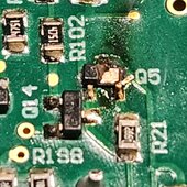
I can't tell you exactly where the voltage for the AFCI comes from, but it's possible that plug in power card on the PMB is responsible. I would attach a meter to the AFCI pins and when booting from battery see when you get voltage there. I assume and hope it's about the same time all the little lights come on around the boards. If so, I would shut down and remove that horizontal plug-in card from the PMB. Then boot again from battery just long enough to see what power appears at the AFCI pins. It may be there is a short of some sort on that small card which is pulling the 12v down, or that card may be responsible for the 12v and isn't up to the task. You'll know either way with the test above because the voltage will change at the AFCI pins with the card removed. The concern I have with this test is that I don't know if it's safe to boot and run the Skybox with that card removed. I pulled the card on mine and did a brief bootup, which is how I located the shorted EMI filter. But, I didn't let it run past the initial turn on of all the little lights. I shut it down immediately, and I'm suggesting the same to you.

Good luck!
 
Very helpful. i noticed all of the test points on the backplane the "support" tech at outback would not tell me what they were or where they were connected to. I have bought a new skybox which a local power store had as a last in stock, when I get it mounted I'll A/B the test points and see where things go. Bit of a costly solution but I only paid 1200 dollars for the first eBay one and since it's used I can't claim the tax credit. The new one just about covers that, I figure it's worth resurrecting the old one and throw it back on eBay
 
So I ended up getting a brand new skybox and was going to take the loss on the used one but the new inverter has a bad mains relay that welded closed. They are sending me another top piece so I took apart the 2 dead inverters before I sent them to the recycling center. Removed the main board to have a look and behold the first used unit has a roasted buffer transistor and looking at box 2 with the stuck relay I can more or less make out the part numbers on the transistors. I also got a new relay and replaced the welded one, going to put it back together tomorrow and see if it will run. Hopefully I end up with 2 used inverters that will make me back a few bucks.
 

Attachments

  • 20240128_204732.jpg
    20240128_204732.jpg
    182 KB · Views: 5
  • 20240128_204605.jpg
    20240128_204605.jpg
    191.6 KB · Views: 5
If anyone has built one of the AFCI bypass devices, please post whether it's working for you or not. Mine has been perfect, but I'd like to know if it's working for anyone else.
 
Back
Top