I have 2 Questions on connecting current carrying wires for JBD BMS (in this case 100A Smart BMS) -
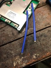
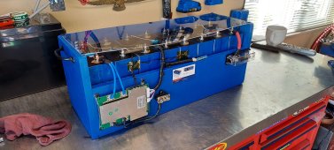
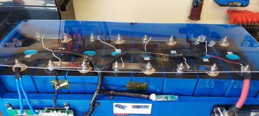
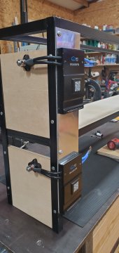
First Question -- How do you people wire these to the battery terminals or negative output battery post ? They are definitely too short as is to reach the terminals in my case I am using 100+AH prismatic Cells . I've seen some 'shoddy' soldering done by some Will Proust tear downs of batteries. I really would rather have a much cleaner connection. I have quality heavy gauge wire crimpers and I like the neatness of a good compression crimp. But what would I do? Strip back more insulation and double up the two wires into one heavy duty crimp and then use a 2 or 4 gauge wire on the other side ???
Come on people show me pics on how you did this ? Neatness and quality of connections are important to me .
Second question -- For you Electrical Engineers - How much current do these two 10 Gauge wires spec'ed to carry while in parallel ? Do you just add up the cross sectional area of the wires and get the closest wire gauges? 10 Gauge wire has cross sectional area of 5.26mm so doubling that is 10.5mm -- which is close to 7 gauges (Which is speced at max current about 90 A) ? Is that right ?