diy solar

diy solar

280A 24V - 3x 340W solar - victron 3KVA inverter/charger complete design check

I just checked and I remember correctly- the smart shunt does not have a relay - for a relay you will need a BMV-712(or others in that lineup)
Thanks for the info.

I already bought the BMV-712. I wish it had two relay outputs so I could use one for charge control and one for discharge control. That would really simplify configuring my system. I wouldn't have to program 3, low voltage disconnect devices. I am pretty much 100% Victron, but unless I add a GS system, I have to use relay logic to control things (except for my SmartSolar, that talks via BlueTooth to the BMV-712). I hope Victron roles out updates for the Orion-TR SmartCharger and Multiplus to let them communicate over BlueTooth. I would buy the BlueTooth dongle in an instant for the Multiplus if it supported being controlled by Victron.Connect.
 
Your wiring diagrams are beautiful :)

What app did you use?

Thanks.
any vectorial drawing program can do it, I am using adobe illustrator, but is like killing a fly with a cannon... freehand, CorelDraw etc can do it. is just what you get used to using... there are a bunch of free programs you can use too.
 
Your wiring diagrams are beautiful :)

What app did you use?

Thanks.

This is a free online drawing tool that a few of us are using:


Here are a couple threads on drawing tools:


Instead of the BMV-712 can you use the Victron SmartShunt 500A? it has a temperature sensor and Bluetooth , not sure if he can talk with the multiplus ...

I was going to ask why you were not using a VE.Direct Battery monitor from Victron since you are using so much other Victron equipment. Yes you can use the SmartShunt if you don't need a dedicated display and will just use your phone. It also works with Venus OS on CerboGX or Raspberry Pi.
 
This is a free online drawing tool that a few of us are using:


Here are a couple threads on drawing tools:


Works great. Thank you.
 
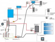
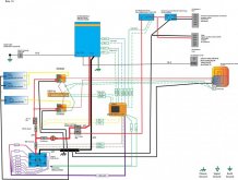
Ok , here my revied version , try to keep it simple but i am not sure I am doing the right thing, the reason behind this design is:
- I want to minimize ghost loads of a 300A big BMS
- I am using brand new cells (hope they do not go out of balance quick)
- I will mainly charge with solar
so my main idea is to have the victron multiplex connect directly to the battery and use the BMS only to take care about the solar charging and the 12/24V loads so i can use a 100A BMS.
Dose make any sense ? or once again I make things too complicated and I have just need to find a 250 or 300A BMS, comment and suggestion appreciated (pdf for readability attach) schema elettrico bms on loads and solar.jpg
 

Attachments

  • schema elettrico bms on loads and solar.pdf
    352.9 KB · Views: 9
Last edited:
Your shunt is still in the wrong place. To properly measure all loads, the wiring should be like this:

Battery (neg) -> BMS -> shunt -> negative distribution bus bar -> everything else.

I would wire the negative wire of the 24v fusebox off of the main negative distribution bar, not the negative stud on the Orion DC-DC Converter. That's just me, I like to keep things as tidy as possible. I don't like to daisy-chain things together.

You have a switch between the Lynx distribution bus bar and the Victron Orion. The Orion supports a remote on/off switch, which would be a much lower amperage rating than the switch you have in the drawing. The downside to that is that you would still need a switch on the 24v side.

Do you really have that many 24v DC devices to justify a 24v DC leg? 24v devices are not common. If a 24v device fails in the field, you're unlikely to find a replacement nearby. 12v devices - such as a water pump - are readily available. SeaFlo water pumps are one of the exceptions that I'm aware of. Most of theirs are dual voltage. The popular Fantastic Fan is 12v only as far as I know.

A 100 amp fuse may not be big enough for the circuit going to the inverter. My puny 1000 watt inverter calls for a 150 amp breaker.

The 80 amp circuit breaker coming out of the solar charge controller is oversized. 60 amp is more appropriate.
 
Thank you for all the advice !
Your shunt is still in the wrong place. To properly measure all loads, the wiring should be like this:

Battery (neg) -> BMS -> shunt -> negative distribution bus bar -> everything else.
I can not put the BMS before the shunt because I have not all the current going true the BMS
The BMS I put is a 100A and can only handle solar charger and the 12 and 24V load for sure not my 3kv inverter
I thought you always put a shunt last thing before your negative battery pole, If to operate the BMS you have to have it before the shunt i have to put 2 shunts, one as you say after the BMS and one on a separate line before the Victron inverter/charger. and do some math between combined numbers...... or get a 250/300 A BMS and follow your instruction.
I am following some treads on the BMS section but nothing is much convincing me.
I would wire the negative wire of the 24v fusebox off of the main negative distribution bar, not the negative stud on the Orion DC-DC Converter. That's just me, I like to keep things as tidy as possible. I don't like to daisy-chain things together.
absolutely right
You have a switch between the Lynx distribution bus bar and the Victron Orion. The Orion supports a remote on/off switch, which would be a much lower amperage rating than the switch you have in the drawing. The downside to that is that you would still need a switch on the 24v side.
one more reason to take off the 24V side , and for the occasional need i need to disconnect remove the fuse
Do you really have that many 24v DC devices to justify a 24v DC leg? 24v devices are not common. If a 24v device fails in the field, you're unlikely to find a replacement nearby. 12v devices - such as a water pump - are readily available. SeaFlo water pumps are one of the exceptions that I'm aware of. Most of theirs are dual voltage. The popular Fantastic Fan is 12v only as far as I know.
You are right 12V is much more common for devices. I got already most of the load on 12, I was planing to search for what left for me to acquire on 24 to skip the step-down and relative extra 3/5% lost conversion, but you raise a really good point
A 100 amp fuse may not be big enough for the circuit going to the inverter. My puny 1000 watt inverter calls for a 150 amp breaker.
yes was a number left behind in the redrawing I need a 300A
The 80 amp circuit breaker coming out of the solar charge controller is oversized. 60 amp is more appropriate.
sound great.
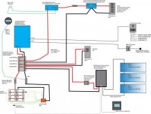
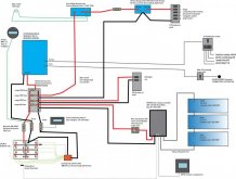
So here 2 designs
one with the 300A BMS (that i still have to find one ) in this case will you remove the
low voltage disconnector Victron BatteryProtect 12/24V-100A or keep it for redundancy on the BMS ?

big BMS 300A.jpg

and one with 2 shunts and 100A BMS

schema elettrico bms on loads and solar 2.0.jpg
are those reasonable solutions in your opinion?
(in attach the pdf versions for more definition)
 

Attachments

  • big BMS 300A.pdf
    355.3 KB · Views: 2
  • schema elettrico bms on loads and solar 2.0.pdf
    358.4 KB · Views: 1
With the other Victron items, I would highly recommend changing the shunt to the Victron Bmv712, that shunt is 500a.
also give strong consideration to moving the solar controller to a Victron Smart controller. By having both the BMV & Solar controller Victron Smart units the BMV can pass temperature and voltage info to the solar controller.
The CCGX (or other Victron GX device) can monitor your whole system in one spot. It will control the Multiplus, see battery info from BMV and see solar charging from the MPPT’s. Because it see’s all devices it can tell (by math) how large your DC loads are. It’s that final step that ties everything up in a bow. Watch a few YouTube’s about it. I think it is worth it.
 
I noticed another item you have three solar panels with Vcc of 45 volts hooked to to a 150/45 mppt. I think that is getting too close to the max voltage- you may hit it on a cold day when conditions are just right. Hitting the max voltage just once usually causes Mppt’s to go poof and die. Can you fit another panel on the roof? If so go 2p2s. (More solar power - less voltage) If not they may need to be wired in parallel.

if you want a shunt to monitor the solar production (and that’s the reason for two shunts) you need to move it between the mppt and the big distribution panel. Then move the negative wire from your BMS onto the Victron shunt.
 
The design with all negative going through the BMS is good.

As far as finding the right BMS, do you know that you need more than 100 amps on the 24v side? I went with two 4s 12v batteries, each with their own BMS. That gives me a rating of 200 amps of throughput. I don't think I'm likely to see that, unless I use my LiFePO4 batteries to start my on-board Onan generator. You could go with an identical second 8s bank and the 100 amp BMS to get 200 amps. However, that's a rather expensive solution. A 300 amp BMS on as 280 Ah 24v battery may not be appropriate anyhow.
 
I noticed another item you have three solar panels with Vcc of 45 volts hooked to to a 150/45 mppt. I think that is getting too close to the max voltage- you may hit it on a cold day when conditions are just right. Hitting the max voltage just once usually causes Mppt’s to go poof and die. Can you fit another panel on the roof? If so go 2p2s. (More solar power - less voltage) If not they may need to be wired in parallel.

if you want a shunt to monitor the solar production (and that’s the reason for two shunts) you need to move it between the mppt and the big distribution panel. Then move the negative wire from your BMS onto the Victron shunt.
Everyone is pushing me to go all the way victron :D FINE! I though to return my actual MPPT and go Victron, so i when on they website to see what unit they suggest
I enter al the info 3 panel in series, Pmax 340W, Vmp 37.6V, Imp 0.05A, Voc 45.9V, Isc 9.62A and they say you need :
SmartSolar MPPT 150/35 ,

Max. input voltage: 150 V
Max. PV voltage @ min. temperature: 137.7 V
Min. input voltage @ MPP: 25 V
Min. PV voltage @ max. temperature: 112.3 V
Max. output current: 35 A
Max. current @ MPP min. temp.: 35 A * Power limiting @ low temp.
Max. current @ MPP max. temp.: 35 A ** Power limiting @ high temp.

so even less margin than my old choice... what you think?
no room for more solar panels :(
 
The design with all negative going through the BMS is good.

As far as finding the right BMS, do you know that you need more than 100 amps on the 24v side? I went with two 4s 12v batteries, each with their own BMS. That gives me a rating of 200 amps of throughput. I don't think I'm likely to see that, unless I use my LiFePO4 batteries to start my on-board Onan generator. You could go with an identical second 8s bank and the 100 amp BMS to get 200 amps. However, that's a rather expensive solution. A 300 amp BMS on as 280 Ah 24v battery may not be appropriate anyhow.
Thank you for your input, I have to instruct myself more on BMS
I was thinking sizing the BMS is not related to the size of your battery banks but the current you are taking out or putting in (A). So in my mind if the BMS is handling only the 24 to 12V load and the solar panels it had to handle only 50A (the multiplex was not controlled by the BMS !
That why the ground of the Victron Multiplex was straight to the battery) so the BMS could do balance only using on the solar input and 12V load).
In my second scenario, I use a BMS to handle the current of all my loads I will need a big BMS. The more hungry service will be the Inverter, Is a 2400W so 100A on 24V with a Peak of 6000W you have 250A on 24V, yes I have to add some loss and the 12V loads but i do not think I am to much out, 10%? . I think a 300A BMS should be enough. I am doing something wrong on my calculation? Any suggestion on what brand model of BMS look into (I am in Canada...)
 
On the MPPT 150/35 - with those three panels it completely maxes out the 150/35. That mppt can deliver 35amps of power @24v - which is 1000 watts. Your panels could deliver 1020 watts, so that is pretty perfect! Looking at the top drawing (Which I think is the better one), I would add a breaker between the solar panels and the mppt - the same kind as between the mppt and distribution box. The purpose for this breaker is so you can disconnect the solar panels from the mppt for testing. It is better to kill the power entering the mppt than to kill the power between it and the battery.

On the BMS - you want the entire battery controlled by the BMS. That way if the battery get to critical mode - it shuts down. The only way it can do that is if all the power is controlled by the BMS. I think you are correct in your calculations and would be looking at the 300 amp bms's.

I am facing the same challenge except in 12v. My Multiplex 12/3000 is the most hungry, except I will be limited to 400a @12v by a fuse. Plenty to max out the normal usage and even have a surge. In my MotorHome I can pick any one high draw item (and only one) front A/c, rear a/c, microwave, & elec. water heater. The inverter can handle one plus the fridge on electric and lights. I imagine you will have the same choice. (I figure the elec water heater or A/c's will completely drain the battery in a about three or four hours - so I probably won't use them on battery).

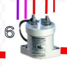
One other option on the BMS (don't ya love all the choices we have) is to use an independent contractor and small bms. I have a Kilovolt EV200AAANA that will be the on/shutoff switch for the power from the batteries. By using the BMS to control the contractor, you don't need a large BMS.


Pict
EV200.JPG

Just something else to think about. (all those red and colored lines are from my battery drawings - not nearly as nice as yours).

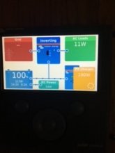
Since I was doing pictures I found one from last year of my CCGX (sorry the light wasn't completely correct).
IMG_1808.JPG

This is what I like about the CCGX - you can see & control everything in one place. The little blue dots are in motion showing the current flows - from the solar to the batteries and to the DC Power.

Well good luck in your decisions

Rocketman
 
alvise, you definitely want to size the BMS to the loads, not necessarily the size of the battery. However, a 300 amp BMS on a 280 Ah battery may be expecting too much out of your battery. You're in a real pickle there. Multiple batteries would help. But stepping down to a 2K inverter would also.

Have you verified that three panels will fit on your van, including avoiding obstructions? If you had four panels instead of three, you could do 2s2p and that configuration would fit well within the specs of a victron 150 or the EPEVER you already have. Alternatively, maybe you could fit four smaller panels instead of three large ones. Otherwise, you need to move up to a higher capacity solar charge controller like the Victron 250 series.

My original plan was for four 200 watt panels. Using a CAD program I found that I couldn't fit those four panels on the roof of my RV trailer. I switched to two 320 watt panels. If you plan to use Z brackets to mount the panels, keep in mind that the brackets add about 1.5" of width on both sides of the panel.
 
On the MPPT 150/35 - with those three panels it completely maxes out the 150/35. That mppt can deliver 35amps of power @24v - which is 1000 watts. Your panels could deliver 1020 watts, so that is pretty perfect! Looking at the top drawing (Which I think is the better one), I would add a breaker between the solar panels and the mppt - the same kind as between the mppt and distribution box. The purpose for this breaker is so you can disconnect the solar panels from the mppt for testing. It is better to kill the power entering the mppt than to kill the power between it and the battery.
yes a disconnector on the solar panels is a good idea because of the voltage i guess you need a different style than the 12/24V v .. need to check specs. I also want to put all the ground connections to the chassis in the drawing that are pretty important.
On the BMS - you want the entire battery controlled by the BMS. That way if the battery get to critical mode - it shuts down. The only way it can do that is if all the power is controlled by the BMS. I think you are correct in your calculations and would be looking at the 300 amp bms's.
In the drawing with the BMS not controlling the multiplex I was thinking that the BMS has his own controls to not damage the battery, for this reason, i left it out and let the BMS take care only of the solar and low voltage loads... but I understand everything under BMS is better insurance for your batteries.
I am facing the same challenge except in 12v. My Multiplex 12/3000 is the most hungry, except I will be limited to 400a @12v by a fuse. Plenty to max out the normal usage and even have a surge. In my MotorHome I can pick any one high draw item (and only one) front A/c, rear a/c, microwave, & elec. water heater. The inverter can handle one plus the fridge on electric and lights. I imagine you will have the same choice. (I figure the elec water heater or A/c's will completely drain the battery in a about three or four hours - so I probably won't use them on battery).

One other option on the BMS (don't ya love all the choices we have) is to use an independent contractor and small bms. I have a Kilovolt EV200AAANA that will be the on/shutoff switch for the power from the batteries. By using the BMS to control the contractor, you don't need a large BMS.
that was one option I was considering, I saw there are also BMS with built-in a contactor,
looks like they are pretty hungry on power and better put a good heat sink on those things.
Solid-state disconnector I think are more reliable and quicker but $$$
I was trying to design something that has a 100 A BMS that handle directly the current from my MPPT solar and low voltage charges and it drives a mechanical contactor that feeds the multiplex. so when i do not need the multiplex i can disconnect with a switch the power to the disconnector so i do not have any ghost load but I can still use all the 12V loads what do you think?

Pict
Just something else to think about. (all those red and colored lines are from my battery drawings - not nearly as nice as yours).
Since I was doing pictures I found one from last year of my CCGX (sorry the light wasn't completely correct).
View attachment 30800

This is what I like about the CCGX - you can see & control everything in one place. The little blue dots are in motion showing the current flows - from the solar to the batteries and to the DC Power.

Well good luck in your decisions

Rocketman
still working on the CCGX, looking I am will be buried on Victron stuff unless I start to play with raspberry pi...
are you all wired or use Bluetooth? what MPPT do you use? make sense to have Bluetooth or you can just wire everything?
Thanks for all the sugestions
 
alvise, you definitely want to size the BMS to the loads, not necessarily the size of the battery. However, a 300 amp BMS on a 280 Ah battery may be expecting too much out of your battery. You're in a real pickle there. Multiple batteries would help. But stepping down to a 2K inverter would also.
those victron 3000 are 2400 W I use for limited time power tools so that what I need to stay away from the 2000, I have small gen that can also give a hand to bump up power when for short time I need more juice...
Have you verified that three panels will fit on your van, including avoiding obstructions? If you had four panels instead of three, you could do 2s2p and that configuration would fit well within the specs of a victron 150 or the EPEVER you already have. Alternatively, maybe you could fit four smaller panels instead of three large ones. Otherwise, you need to move up to a higher capacity solar charge controller like the Victron 250 series.
the van is a "cube" van style a unicel fibreglass, just perfect fit :D
i have also already the panels
My original plan was for four 200 watt panels. Using a CAD program I found that I couldn't fit those four panels on the roof of my RV trailer. I switched to two 320 watt panels. If you plan to use Z brackets to mount the panels, keep in mind that the brackets add about 1.5" of width on both sides of the panel.
i will have a long angle aluminum L rail all along the roof with panels mounted with long side across.
still not sure why victron with all the spec supply say The victron website say I need a 150/35 , yes I feel i am a little bit on the line... not sure if stay with it and put a fuse ... just in case
 
Last edited:
Alvise, I just realized two more items that may be needed.

First, A power cutoff switch. You probably want this just before or after the main fuse on your main positive line. You could use your fuse to cut power to the system, but a good on/off switch is very nice.

Second, Current In rush protection. (according to my understanding). When the big inverters first power up, the capacitors need a lot of power, and there will be a massive current in rush to the invertor. This in rush will create a very large spark and is not good for the invertor, power switch, or switching electronics in the BMS. In a couple of Will's video's he demonstrated it. The capacitors only discharge if not connected to power for a while. According to my research, there is several ways to get around it.

1. Use Lead Acid batteries, they cannot deliver the large current inrush and have higher resistance - so no problems. (But this kinda defeats the whole lithium battery thing...)
2. Manually bypass the BMS with a wire (or a resister) to close the circuit for a moment to charge the invertor's capacitors. This is what Will did in his video's. Then engage the BMS.
3. I think the capacitors also may charge if connected to 120v - so connect to 120v before flipping the switch on the 12v.

I found two different installation solutions.

4. On Battleborn's website they have a "Current Surge Limiter
5. Rec-BMS has a Pre-Charge unit. (This is what I chose to do w/ my contractor.

I don't know for sure if this matters on our 3000watt inverters, (Battle Born says its needed on 4000 Watt Inverters for their BMS's). But I figured I would bring this up for you to think about.
 
The reason Victron pointed you to the 150/35 is you don't need anything bigger. Anything bigger is just wasted capacity. Your panels will max out at 137v @min temp - so you need a 150 volt mppt. A 35 amp mppt will handle 1000 watts of solar panels. You have 1020 watts (at perfect conditions), they will never produce the full 1020 watts, they will be a little dirty, flat mounted, sun won't be directly overhead, so your panels will never out produce your mppt. If you choose to get a 150/45 it will never produce over 35 amps - so you don't need to get the higher capacity.

One trick you can do (works better with lead-acid batteries), is to have slightly more panels, than the mppt can produce in amps. On my rig I put four 200 watt panels in a 2p2s and used a Victron mppt 100/50. They max out at about 22 volts , so combined my voltage is under 45 volts (way under the 100 volt limit). However In perfect conditions they could produce 800 watts which 800/14.4volts = 55.6 amps. The mppt can only produce 50amps, so on those perfect times I will lose out of some power - it is clipped. (Exceeding the mppt a little on this side doesn't hurt Victron's). Since it was installed I only saw the mppt get pegged at 700 watts only once. But having the extra panels was nice the rest of the time.
 
Last edited:
Ok , here my revied version , try to keep it simple but i am not sure I am doing the right thing, the reason behind this design is:
- I want to minimize ghost loads of a 300A big BMS
- I am using brand new cells (hope they do not go out of balance quick)
- I will mainly charge with solar
so my main idea is to have the victron multiplex connect directly to the battery and use the BMS only to take care about the solar charging and the 12/24V loads so i can use a 100A BMS.
Dose make any sense ? or once again I make things too complicated and I have just need to find a 250 or 300A BMS, comment and suggestion appreciated (pdf for readability attach) View attachment 30666

I'd put a high current disconnect between the main battery fuse and the lynx distributor so you can kill the entire system with one switch.

You need a disconnect on the PV side of your charge controller; this is code in most countries.

You could use a smaller SSR or battery protect for just the 24V device fuse block and then a separate run from the Lynx to the Orion 24 to 12 and use it's remote enable/disable controlled by the BMS.
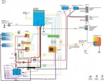
Thanks for the input, using a different style of BMS is exactly what I am thinking now. I do not feel to confident about the user interface and control of parameters of the BSM i saw (except overkill ) So i am planning to totally change the design and use electrocacus , I can also integrate the solar control get rid of the big MPPT (that i discover because of design and components could have a limited lifespan. so in attach a schema elettrico electrodocus.jpg

complete redesign of the system, PD for better resolution , probably still some tweaks, i will expand on the AC side, GFI etc.. any suggestion and help welcome.
 

Attachments

  • schema elettrico electrodocus.pdf
    396.9 KB · Views: 16
Thanks for the input, using a different style of BMS is exactly what I am thinking now. I do not feel to confident about the user interface and control of parameters of the BSM i saw (except overkill ) So i am planning to totally change the design and use electrocacus , I can also integrate the solar control get rid of the big MPPT (that i discover because of design and components could have a limited lifespan. so in attach a View attachment 31646

complete redesign of the system, PD for better resolution , probably still some tweaks, i will expand on the AC side, GFI etc.. any suggestion and help welcome.
This looks very similar to my own system. I think you'll be happy with the Electrodacus BMS. A couple observations:

You need to power the DEXT16. There is a "+" and a "-" terminal that need battery power.

On your diversion water heater--not sure what you're using, but the two elements should be different resistances matched to the panels if you want to maximize power, since you have 2 solar panels feeding one element and only 1 panel feeding the other. You note 36V, which I'm assuming is what you expect will come from the panels--but this will depend on resistance chosen. Your solar panels are current sources of about 9A each in full sun. So one element will get up to 18A, the other up to 9A. To get about 36V on both elements to be near Vmp for the solar panels, you would need about 2 ohms on the first element and 4 ohms on the second. This would give you a total maximum heating power of roughly 1000W.

Minor point--you have your load control lines going to your DC loads color coded green, I think you meant it to be blue like other load control lines.

EDIT: A comment on diversion--I considered using that but then decided just to power my water heater from AC from the inverter. That way I have reliable hot water regardless of whether there is excess solar or not. If you do have excess solar, then of course your battery bank is full and so running your inverter is not an issue. The only (minor) downside I see is the inverter losses, but again if you do have excess solar it's not an issue. And when you don't have excess solar, you can still have hot water.
 
Last edited:
This looks very similar to my own system. I think you'll be happy with the Electrodacus BMS. A couple observations:

You need to power the DEXT16. There is a "+" and a "-" terminal that need battery power.

On your diversion water heater--not sure what you're using, but the two elements should be different resistances matched to the panels if you want to maximize power, since you have 2 solar panels feeding one element and only 1 panel feeding the other. You note 36V, which I'm assuming is what you expect will come from the panels--but this will depend on resistance chosen. Your solar panels are current sources of about 9A each in full sun. So one element will get up to 18A, the other up to 9A. To get about 36V on both elements to be near Vmp for the solar panels, you would need about 2 ohms on the first element and 4 ohms on the second. This would give you a total maximum heating power of roughly 1000W.

Minor point--you have your load control lines going to your DC loads color coded green, I think you meant it to be blue like other load control lines.

EDIT: A comment on diversion--I considered using that but then decided just to power my water heater from AC from the inverter. That way I have reliable hot water regardless of whether there is excess solar or not. If you do have excess solar, then of course your battery bank is full and so running your inverter is not an issue. The only (minor) downside I see is the inverter losses, but again if you do have excess solar it's not an issue. And when you don't have excess solar, you can still have hot water.
thanks a lot, a really good point for using the inverter for heating water, easier to work with a 120V heating element. Did you have some kind of automatic system to activate the heating of the water with the inverter when you have overproduction on solar? I guess you can use the signal of the BMS in series to the thermostat...
Last thing there is any grounding wiring of the Electrodacus I am missing?
Any suggestion for the 300Amp Circuit Breaker, will you have to take care of any surge current?
 
thanks a lot, a really good point for using the inverter for heating water, easier to work with a 120V heating element. Did you have some kind of automatic system to activate the heating of the water with the inverter when you have overproduction on solar? I guess you can use the signal of the BMS in series to the thermostat...
I have not yet used my new electrical system yet. I've had it working on my bench with the Electrodacus BMS for some months but now moving into the van.

But I don't think an automatic diversion system is needed for a van. You'll probably be turning off your inverter when not using AC anyway, so you don't have no-load current drain 24/7. If you do have excess solar, you will be at 100% SOC so just run the inverter.

But if you do want it automatic, I think you could configure one EXTIO output to Type 4 with an SOC threshold so that its contacts are closed above that threshold and open below, and connect in series with your thermostat contacts. Since you've already used up your existing EXTIO connections, you'd need to add another optocoupler board to get more connections.

I have an Isotemp water heater and it has both an AC element and also engine coolant connections, so I'll also be able to have hot water from waste engine heat. Everyone that has these heaters says they hold heat for 24 hours. So your morning drive can heat the water for the day without even needing to run the inverter. I'm putting an inverter remote power switch in easy reach at my galley.

Last thing there is any grounding wiring of the Electrodacus I am missing?
I didn't see anything else missing on BMS connections. You do have separate EXTIO pairs going to each device, which is good. People new to this BMS sometimes make the mistake of connecting multiple devices to one EXTIO pair. Only works if the devices have same input specs and collectively don't exceed the optocoupler max current (70mA if I recall).

One other thing, if you're a belt and suspenders guy you can add an extra layer of protection using Type 5 connected to the remote power switch on the Multiplus, in addition to using the Aux inputs for normal charge control. Type 5 is a safety lock that turns off on any of several fault conditions. You can set wider limits than for normal operation. And the Multiplus remote power switch physically powers the unit on and off, vs. the Aux inputs that drive firmware. But you'd need another EXTIO pair since you've used up your existing pairs.

Why use this? It's possible to have error conditions such as a user error (inadvertantly set limits wrong, or set up Aux inputs wrong, download a FW update and unknowingly disable the Aux inputs...) or even a FW bug in the Multiplus or even the BMS. Things happen. Ironically, I actually found a bug in the Type 5 function (which Dacian fixed in a day). That's why the manual says Type 5 only works correctly after version 4.1p.
Any suggestion for the 300Amp Circuit Breaker, will you have to take care of any surge current?
I don't use a breaker, just the Class T fuse. Along with a battery switch for an inverter disconnect. You do need to pre-charge--the inverter input caps are very large and you can get 1000s of amps which will arc and damage the switch contacts over time. But pre-charging is only necessary when connecting the inverter. In normal operation, the inverter switch will remain in the on position and no need to pre-charge.

You can do it with a wire as Will does in his videos. But I don't like the spark so I used a wire with an added resistor to pre-charge when building and testing my system. Finally I decided to implement a simple pre-charge circuit using a Blue 4-position battery switch and a 12.5 ohm resistor made from two 25 ohm power resistors in parallel. I estimated the input capacitance at about 25 mF, so that makes a time constant of about 300ms. Pausing on the pre-charge position for about 1 second to get above 95% pre-charge. Peak power dissipation in the resistor is about 63W but it is short, and these are rated 50W each.

Connections:
Output: connect to positive bus bar (yes the switch is bi-directional, I'm using output as input)
Input 1 to Input 2: 12.5 ohm power resistor connected between these two terminals
Input 2: output connection to inverter

Operation:
I labeled it with an arrow to move counter-clockwise only. Sequence is then OFF -> 1 -> 1+2 -> 2 -> OFF
OFF: no connection
1: Battery connected to inverter through the power resistor--pre-charge position--pause here for 1 second
1+2: Battery connected directly to inverter--operating position
2: Battery connected directly to inverter--also a valid operating position
OFF: back to no connection
 
But I don't think an automatic diversion system is needed for a van. You'll probably be turning off your inverter when not using AC anyway, so you don't have no-load current drain 24/7. If you do have excess solar, you will be at 100% SOC so just run the inverter.

But if you do want it automatic, I think you could configure one EXTIO output to Type 4 with an SOC threshold so that its contacts are closed above that threshold and open below, and connect in series with your thermostat contacts. Since you've already used up your existing EXTIO connections, you'd need to add another optocoupler board to get more connections.
I really like the idea of using the SOC to control the automatic system the problem is that if i want hot water and the battery is not full it will not heat the water so i think i will put in parallel to the automatic switch a toggle switch so i can heat water also if battery not full..
Anf you are right i will not keep the inverter on all time to reduce consumption so I would like to planning to turn on the inverter automatically in the case is off and there is solar power extra production, does it make sense? still, try to think of how to do it in e elegant way ... maybe out of the EXT IO6+ with optocoupler? Or using the EXT IO6+ , but it need to be open when close and close when open to controll the switch on the victron...(not sure i can express myself...)
One other thing, if you're a belt and suspenders guy you can add an extra layer of protection using Type 5 connected to the remote power switch on the Multiplus, in addition to using the Aux inputs for normal charge control. Type 5 is a safety lock that turns off on any of several fault conditions. You can set wider limits than for normal operation. And the Multiplus remote power switch physically powers the unit on and off, vs. the Aux inputs that drive firmware. But you'd need another EXTIO pair since you've used up your existing pairs.

Why use this? It's possible to have error conditions such as a user error (inadvertantly set limits wrong, or set up Aux inputs wrong, download a FW update and unknowingly disable the Aux inputs...) or even a FW bug in the Multiplus or even the BMS. Things happen. Ironically, I actually found a bug in the Type 5 function (which Dacian fixed in a day). That's why the manual says Type 5 only works correctly after version 4.1p.
is in, sounds like a great idea, just not sure if makes sense also to control the 12/24 battery protector and the solar charging side.
In theory, the battery protector should already provide the protection, and also probably if something in the BMS fails you will be happy if you can still have your 12 and 24 circuits going..
About the solar charging side is probably good to disconnect (optocoupler too with the 2 different signals? the regular one from the SBMS0 EXTIO4 and one from what in my drawing is EXTIO5 ?)
I don't use a breaker, just the Class T fuse. Along with a battery switch for an inverter disconnect. You do need to pre-charge--the inverter input caps are very large and you can get 1000s of amps which will arc and damage the switch contacts over time. But pre-charging is only necessary when connecting the inverter. In normal operation, the inverter switch will remain in the on position and no need to pre-charge.

You can do it with a wire as Will does in his videos. But I don't like the spark so I used a wire with an added resistor to pre-charge when building and testing my system. Finally I decided to implement a simple pre-charge circuit using a Blue 4-position battery switch and a 12.5 ohm resistor made from two 25 ohm power resistors in parallel. I estimated the input capacitance at about 25 mF, so that makes a time constant of about 300ms. Pausing on the pre-charge position for about 1 second to get above 95% pre-charge. Peak power dissipation in the resistor is about 63W but it is short, and these are rated 50W each.
that is really smart, but maybe I pass it, more hardware and contacts...
I also add
- brake to disconnect solar panels
- switch to remotely tur on of inverter in parallel with the other controls
- temperature sensor to the victron
with this configuration i think I don't really need the DEXT16 and the DSSR20 with diverter, but i already order them ....
Thanks again for all the help and suport.schema elettrico electrodocus 20.jpg
 

Attachments

  • schema elettrico electrodocus 20.pdf
    416.5 KB · Views: 2

diy solar

diy solar
Back
Top