I have 3 of the basic model eg4 48v 100ah batteries. I'm not using a server rack and was going to connect each battery in parallel with 4/0 wire. I was then going to run power from top battery and negative from bottom battery also using 4/0 to my busbar and fuses. Is this overkill for wire or as I like to say I rather have more than enough than too little.
You are using an out of date browser. It may not display this or other websites correctly.
You should upgrade or use an alternative browser.
You should upgrade or use an alternative browser.
(3) EG4 48v 100ah basic model battery in parallel without server rack
- Thread starter Matt3
- Start date
FilterGuy
Solar Engineering Consultant - EG4 and Consumers
The question can't be answered without knowing what the load is. If you are putting a 3K inverter on it I would call it overkill. (3AWG would be large enough)
Each battery can sustain 100A so the largest load you can put on 3 is 300A. The fuse for 300A should be 300A x 1.25 = 375A. If we use the NEC ampacity chart, 4/0 would not be large enough for the wires from the batteries to the inverter. However, if you use the more aggressive ABYC charts, 4/0 is fine.
Note: With the NEC charts, the largest load on 4/0 would be about 275A (After calculating headroom for the fuse/breaker as well as inverter efficentcy)
Given the way you are wiring the batteries, I would use the same gauge wiring them in parallel as I used from the battery to the inverter.
FilterGuy
Solar Engineering Consultant - EG4 and Consumers
For two 6500, 4 AWG is significantly undersized.it will be (2) eg4 6500 inverters in parallel to make split phase.
A 6500W inverter running at 90% efficiency will draw 6500W/.9=7222W from the battery. This works out to 7222W/48V = 150.1A if the battery is low. The fuse or breaker should be sized at 150.1A x 1.25 = 188A. This would round up to a 200A fuse. The NEC requirement for this size wire is 3/0AWG. The combined current for two inverters would be 300A. The fuse size would be 375. The wire size would be 400 or 500 kcmil.
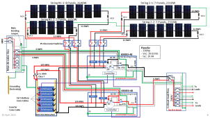
I would recommend finding a way to split the wiring so that no one wire handles all the current. I was just working on a design that is similar:

This uses a battery rack, but you could do something like it with bus bars.
Also, 3 LiFePOWER4 batteries is undersized for the system. It will just barely work. (Each battery can deliver 100A). However, the inverters will drain them in about 1 hour if they are running at full capacity.
Also, make sure the combined charge current of the two inverters is kept below 150A. This is 50A/battery or .5C
Finally, with only 150A of charge current, anything more than about 7800W of panels will start to be a waste.
It's 4/0 not 4 wire size. I also will have each inverter fused with 200amp fuse coming from a common 250amp rated bus bar. the inverterswill be in series not parallel as I said the wrong connection earlier. I will have each inverter going to each leg of my distribution box to provide 240. 6500w x 120v=54 amp
1300w x 240v= 54 amp. That is 54 amp to each leg of distribution box. I will use 6awg to run from inverter to distribution box that will go into a 60amp double pole breaker giving 54amp to each leg coming from inverters. 2/0 will run from inverter to the 200amp fuse for each inverter which will connect to a 250amp busbar terminal block. 4/0 will run from their to the paralleled lead wire coming from battery bank. This will be same for ground side minus the fuses. My question is WHAT SIZE WIRE SHOULD I USE FOR PARALLELING MY BATTERIES? I was going to use 4/0. Is that what I should stick with?
1300w x 240v= 54 amp. That is 54 amp to each leg of distribution box. I will use 6awg to run from inverter to distribution box that will go into a 60amp double pole breaker giving 54amp to each leg coming from inverters. 2/0 will run from inverter to the 200amp fuse for each inverter which will connect to a 250amp busbar terminal block. 4/0 will run from their to the paralleled lead wire coming from battery bank. This will be same for ground side minus the fuses. My question is WHAT SIZE WIRE SHOULD I USE FOR PARALLELING MY BATTERIES? I was going to use 4/0. Is that what I should stick with?
FilterGuy
Solar Engineering Consultant - EG4 and Consumers
Yes. I did a typo. A 4/0 wire is not large enough for all of the current. (It is large enough for a single inverter)It's 4/0 not 4 wire size.
The busbar needs to be rated for at least 300A. Preferably for 375A.250amp rated bus bar
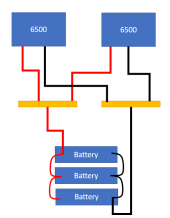
If I understand correctly, this is your layoutMy question is WHAT SIZE WIRE SHOULD I USE FOR PARALLELING MY BATTERIES? I was going to use 4/0. Is that what I should stick with?

The wires from the batteries to the Bus Bar would need to be 300kcmill if you go by the NEC guidlines.
yes this is the system. I have watched the owner of this website build the same system with 6 batteries in parallel and used the exact same wiring system that I explained. the only difference is that he had the eg4 rack with the busbar built onto it. He paralleled through the rack busbar with a smaller wire that I was not sure of the size. then ran 4/0 from the busbar. I also have watched handfuls of videos with smaller and bigger systems use this same wing schematic. You are the only one who I have heard of these numbers you are presenting. I'm not saying you are wrong but you are the only one.Yes. I did a typo. A 4/0 wire is not large enough for all of the current. (It is large enough for a single inverter)
The busbar needs to be rated for at least 300A. Preferably for 375A.
If I understand correctly, this is your layout
View attachment 144098
The wires from the batteries to the Bus Bar would need to be 300kcmill if you go by the NEC guidlines.
timselectric
If I can do it, you can do it.
- Joined
- Feb 5, 2022
- Messages
- 18,619
It's because of the way you are paralleling the batteries.yes this is the system. I have watched the owner of this website build the same system with 6 batteries in parallel and used the exact same wiring system that I explained. the only difference is that he had the eg4 rack with the busbar built onto it. He paralleled through the rack busbar with a smaller wire that I was not sure of the size. then ran 4/0 from the busbar. I also have watched handfuls of videos with smaller and bigger systems use this same wing schematic. You are the only one who I have heard of these numbers you are presenting. I'm not saying you are wrong but you are the only one.
The server rack already has bus bars.
why would that change anythingIt's because of the way you are paralleling the batteries.
The server rack already has bus bars.
timselectric
If I can do it, you can do it.
- Joined
- Feb 5, 2022
- Messages
- 18,619
If paralleled by jumping from battery to battery. The jumpers need to be sized for full output of all 3.why would that change anything
timselectric
If I can do it, you can do it.
- Joined
- Feb 5, 2022
- Messages
- 18,619
I don't know exactly. But, It's designed for 6 x 100a . So at least 600a.
well in that case if I make my own setup that mimics their system to parallel my batteries. Say I get a 400amp rated busbar for power and ground. what size wire would I need to go from battery to busbarI don't know exactly. But, It's designed for 6 x 100a . So at least 600a.
zanydroid
Solar Wizard
nit (EDIT: actually it's more important than a nit): DC+ and DC-power and ground
Best to keep the terminology clear, since many DC systems are ungrounded, and this can be an important distinction when designing/wiring things up.
timselectric
If I can do it, you can do it.
- Joined
- Feb 5, 2022
- Messages
- 18,619
It would depend on the length.well in that case if I make my own setup that mimics their system to parallel my batteries. Say I get a 400amp rated busbar for power and ground. what size wire would I need to go from battery to busbar
If less 5' , I would recommend #4.
Between 5' and 10', I would recommend #2.
For positive and negative.
To avoid voltage drop and loss to heating.
ok. positive and negativenit (EDIT: actually it's more important than a nit): DC+ and DC-
Best to keep the terminology clear, since many DC systems are ungrounded, and this can be an important distinction when designing/wiring things up.
thanks.It would depend on the length.
If less 5' , I would recommend #4.
Between 5' and 10', I would recommend #2.
For positive and negative.
To avoid voltage drop and loss to heating.
making sure that you mean 4awg or 2awg depending on length and not 4/0 or 2/0thanks.
timselectric
If I can do it, you can do it.
- Joined
- Feb 5, 2022
- Messages
- 18,619
Correctmaking sure that you mean 4awg or 2awg depending on length and not 4/0 or 2/0
Similar threads
- Replies
- 3
- Views
- 317
- Replies
- 1
- Views
- 268
- Replies
- 7
- Views
- 241
- Replies
- 23
- Views
- 1K
- Replies
- 1
- Views
- 331


