


Hello friends of sunshine,
My name is Juergen and i live in not-so-hot-and-sunny Austria.")
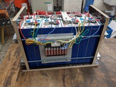
A few days ago, i've finished my 8S / 105Ah LFP backed "balcony power plant" and i'd like to share the experience i've made with this project with you:
* Buying the LFP cells
I've read/watched a lot on the internet and i've finally decided to get my cells from Jenny Wu at DocanTech. I've received the cells in the promised timeframe, also DDP shipment worked perfectly well, the order was placed on alibaba.com and there was no additional tax charged when i picked up the package from our local delivery company (DPD in that case).
The cells were packaged well and did not show any signs of damage, all barcodes on the EVE LF105 cells were readable, copper busbars included - everything fine
I did not have the possibility to measure the internal resistance of the cells, but i have charged ~75Ah into every cell before top-balancing them for a week.
* The BMS
I decided to use a passively cooled 150A Daly Smart-BMS. The main reason i bought this unit was, because I've already managed to get data readouts through the UART interface on a previous "lab setup" (40A Smart-BMS with 4S LFP 6Ah cylindric cells), which was an important factor for me, as i wanted to use a MCU to fetch data from the battery and control my loads through the MCU.
I'm pretty happy with the Daly-BMS, but there are some things which you should be aware of:
* The internal passive balancer of the BMS is completely useless (as we all know i guess)
* the BMS is not able to register low currents (with the 150A version, less than 2A are not recognized) - so you probably do NOT want to rely on the SOC which the BMS reports
* if you are planning to read data through the UART port, make sure to use a digital UART-aware isolator (like ADUM1201) between the BMS and your host system (MCU in my case) or you may fry your electronics sooner or later (ground wire of UART port on the BMS is battery ground, not system ground!)
* Victron SmartShunt and SmartSolar
So as i cannot rely on the Daly-BMS concerning the SOC, i decided to go for the Victron SmartShunt, and also use the SmartSolar charger to be able to benefit from the VE.smartnetworking feature. I'm 100% happy with that setup, i also use the VE.direct UART interface (also with ADUM1201 isolators) to fetch data from both devices, where the SmartShunt is now my primary (and only) source for the SOC on my MCU unit.
* The active balancer
I've decided to get a capacitive active balancer from Heltec and i've wired the "run" pins to a dedicated SSR on my MCU to be able to enable/disable the balancer on demand. Basically i'm using 2 (configurable) parameters to enable the balancer:
* at least one cell in the pack is above 3.4V
* the cell voltage difference between highest and lowest cell is above 30mV
I've added an additional "alarm mode" so the balancer kicks in if the voltage-diff exceeds 100mV at any voltage (SOC) state. However, i think i might kick out this function as i think i understood now thanks to this thread why it's only useful to enable the balancer while the battery is charging (or at least at a high SOC).
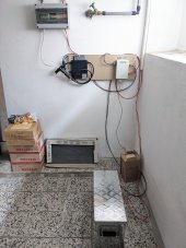
* The PV Panel
I've bought a 460W (STC) chinese panel from a local dealer and until now i'm quite happy with it. The highest power delivered by the panel was ~410W which seems perfectly fine to me, taking into account that the panel's datasheet states an NOCT Pmppt of 346W.
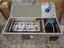
* The Case
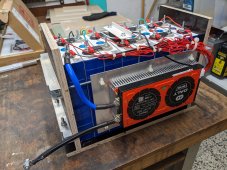
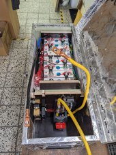
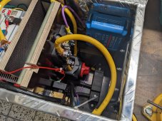
As the battery is located in my basement, i wanted to make sure that the house won't burn down in case something goes wrong, so i put the whole setup (battery, BMS, balancer, Victron devices and fusebox with powerswitch) into an alloy box. Additionally, i've created some sort of "burning chamber" made of drywall and some tiles. As far as i can tell by now, it should be possible to keep the lid of the alloy box closed in terms of heat dissipated inside the case. Even at high PV power, the temperature near the SmartSolar charger (hotspot) in the box did not pass 35°C (95°F), the battery cells stay at 20~25°C.
One recommendation on selecting a box from my side: if you've found a box where you think that everything will fit in - buy the larger version!
* The Micro-Inverter
I've decided to get a Hoymiles HM-300 inverter for several reasons:
* The inverters from Hoymiles are CE certified (which does not mean "china export", as you can think of on many cheap ali-inverters)
* The HM-300 has configurable output power which can be regulated with some cheap hardware and free software. This will allow me to setup zero-feed in the future (as soon as my grid provider gives me the ability to fetch live data from my SmartMeter)
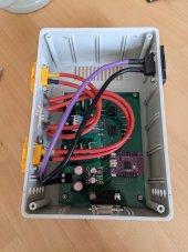
* The MCU
I'm running a Lolin WEMOS S2 Mini ESP32 controller to fetch data through UART ports of the 3 devices and regulate my loads accordingly. The MCU sends data through WiFi to a local MQTT broker and also allows configuration parameters (in example, at which SOC to enable/disable loads) to be fetched by MQTT.
As a frontend, i use FHEM home automation, which has mostly historical reasons (started with FHEM because i use some HomeMatic devices).

I've placed all required sources (soft- and hardware) on Github if you're interested - but be warned: i'm a hobby programmer, so expect spaghetti code at it's finest (hopefully it's at least well documented)!
Attaching some photos of the battery box and additional hardware used.
Have fun and sunny weather,
yours,
Juergen
My name is Juergen and i live in not-so-hot-and-sunny Austria.
A few days ago, i've finished my 8S / 105Ah LFP backed "balcony power plant" and i'd like to share the experience i've made with this project with you:
* Buying the LFP cells
I've read/watched a lot on the internet and i've finally decided to get my cells from Jenny Wu at DocanTech. I've received the cells in the promised timeframe, also DDP shipment worked perfectly well, the order was placed on alibaba.com and there was no additional tax charged when i picked up the package from our local delivery company (DPD in that case).
The cells were packaged well and did not show any signs of damage, all barcodes on the EVE LF105 cells were readable, copper busbars included - everything fine
I did not have the possibility to measure the internal resistance of the cells, but i have charged ~75Ah into every cell before top-balancing them for a week.
* The BMS
I decided to use a passively cooled 150A Daly Smart-BMS. The main reason i bought this unit was, because I've already managed to get data readouts through the UART interface on a previous "lab setup" (40A Smart-BMS with 4S LFP 6Ah cylindric cells), which was an important factor for me, as i wanted to use a MCU to fetch data from the battery and control my loads through the MCU.
I'm pretty happy with the Daly-BMS, but there are some things which you should be aware of:
* The internal passive balancer of the BMS is completely useless (as we all know i guess
)* the BMS is not able to register low currents (with the 150A version, less than 2A are not recognized) - so you probably do NOT want to rely on the SOC which the BMS reports
* if you are planning to read data through the UART port, make sure to use a digital UART-aware isolator (like ADUM1201) between the BMS and your host system (MCU in my case) or you may fry your electronics sooner or later (ground wire of UART port on the BMS is battery ground, not system ground!)
* Victron SmartShunt and SmartSolar
So as i cannot rely on the Daly-BMS concerning the SOC, i decided to go for the Victron SmartShunt, and also use the SmartSolar charger to be able to benefit from the VE.smartnetworking feature. I'm 100% happy with that setup, i also use the VE.direct UART interface (also with ADUM1201 isolators) to fetch data from both devices, where the SmartShunt is now my primary (and only) source for the SOC on my MCU unit.
* The active balancer
I've decided to get a capacitive active balancer from Heltec and i've wired the "run" pins to a dedicated SSR on my MCU to be able to enable/disable the balancer on demand. Basically i'm using 2 (configurable) parameters to enable the balancer:
* at least one cell in the pack is above 3.4V
* the cell voltage difference between highest and lowest cell is above 30mV
I've added an additional "alarm mode" so the balancer kicks in if the voltage-diff exceeds 100mV at any voltage (SOC) state. However, i think i might kick out this function as i think i understood now thanks to this thread why it's only useful to enable the balancer while the battery is charging (or at least at a high SOC).
* The PV Panel
I've bought a 460W (STC) chinese panel from a local dealer and until now i'm quite happy with it. The highest power delivered by the panel was ~410W which seems perfectly fine to me, taking into account that the panel's datasheet states an NOCT Pmppt of 346W.
* The Case
As the battery is located in my basement, i wanted to make sure that the house won't burn down in case something goes wrong, so i put the whole setup (battery, BMS, balancer, Victron devices and fusebox with powerswitch) into an alloy box. Additionally, i've created some sort of "burning chamber" made of drywall and some tiles. As far as i can tell by now, it should be possible to keep the lid of the alloy box closed in terms of heat dissipated inside the case. Even at high PV power, the temperature near the SmartSolar charger (hotspot) in the box did not pass 35°C (95°F), the battery cells stay at 20~25°C.
One recommendation on selecting a box from my side: if you've found a box where you think that everything will fit in - buy the larger version!
* The Micro-Inverter
I've decided to get a Hoymiles HM-300 inverter for several reasons:
* The inverters from Hoymiles are CE certified (which does not mean "china export", as you can think of on many cheap ali-inverters)
* The HM-300 has configurable output power which can be regulated with some cheap hardware and free software. This will allow me to setup zero-feed in the future (as soon as my grid provider gives me the ability to fetch live data from my SmartMeter)
* The MCU
I'm running a Lolin WEMOS S2 Mini ESP32 controller to fetch data through UART ports of the 3 devices and regulate my loads accordingly. The MCU sends data through WiFi to a local MQTT broker and also allows configuration parameters (in example, at which SOC to enable/disable loads) to be fetched by MQTT.
As a frontend, i use FHEM home automation, which has mostly historical reasons (started with FHEM because i use some HomeMatic devices).
I've placed all required sources (soft- and hardware) on Github if you're interested - but be warned: i'm a hobby programmer, so expect spaghetti code at it's finest (hopefully it's at least well documented)!
Attaching some photos of the battery box and additional hardware used.
Have fun and sunny weather,
yours,
Juergen
Attachments
-
 PXL_20230413_175401825.jpg351 KB · Views: 34
 -
 PXL_20230413_175414423.jpg352.7 KB · Views: 37
 -
 PXL_20230421_091031958.jpg239.1 KB · Views: 35
 -
 PXL_20230421_140642598.jpg293.6 KB · Views: 31
 -
 PXL_20230427_140519847.jpg391.7 KB · Views: 32
 -
 PXL_20230505_161825851.jpg142.7 KB · Views: 34
 -
 PXL_20230604_131103833.jpg183.5 KB · Views: 35
Last edited: