1- It's going on my 30' RV tow trailer and we go to many different State/ Fed parks so shading could be an issue. If I were to add two more panels for a total of 6 100w, what would be your suggestions on S/P and placement on the roof?
Your SCC supports up to 100V and 100W panels usually have a Voc in the order of 21.6V, so a 3S2P configuration would use all of your panels and stay within the specs of your SCC.
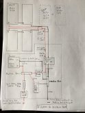
2- if / when I add the DC panel I will def add a main fuse there.
I actually meant a means of cutting off the loads should your battery SoC get to the point that further discharge would damage it. There are other products available but checkout the Victron BatteryProtect modules. But yes, the line should be fused too, the fuse is there to protect the cabling from short circuit.
3- I went with Blue Sea shut off switches between the PV and SCC and at the batteries.
")
4-This is something Ive been undecided about,....
The best way to spec
any cable run it to consider the following three guidelines:
(1) The cable should support the expected load current
(2) The cable run should not drop more than 3% of the voltage across it
(3) The cable and connectors should be suited to the environment it will be operating in
(1) is dead easy, just checkout references such as
this one. For example, if you're planning to have a 1,000W inverter, at peak load, 83A will be flowing on the DC side, and would, therefore, require a minimum of 6AWG or larger cable (btw, you have spec'ed 2AWG which would support up to 170A).
(2) needs a bit of simple maths. Taking your 50' 10AWG cable run as an example, per the link above, 10AWG copper cable has a resistance of 0.61mΩ per foot, so 30.5mΩ across your total cable run (
0.61mΩ per foot x 50' = 30.5mΩ). Assuming you connect your panels in a 3S2P configuration, using your diagram, each string will generate 5.5A, so 11A reaching your MPPT at 54.6V (i.e. 600W). So you cable run will drop 0.34V or 0.6% of the supply voltage (
V=IR = 11A x 30.5mΩ = 0.34V). This is good but it also indicates that you're probably over-spec'ing your cable. Some say that it's always best to over-spec cable but I don't agree with this, over-spec'ing cable just adds unnecessary weight and cost to your project without any appreciable benefit.
Additional note: P=I²R, so the amount of power you lose in a cable run is proportional to the square of the current flowing through it. More current means more losses. For example, a 3S2P configuration would generate 11A or 3.7W losses (
P=I²R = 121A x 30.5mΩ = 3.7W), a 2S3P configuration would generate 16.5A or 8W losses, a 6P configuration would generate 33A or 33W losses in the cable run. So series is better to reduce losses, but parallel is better if shading is a problem. A 3S2P configuration would perhaps be a nice middle ground. If shading is of real concern, maybe a 2S3P configuration would work best for you. But I would certainly avoid an entirely parallel setup.
(3) just needs a bit of research. Cables that are out in the sun 24/7 need to be suited to that environment. 'Proper' PV cable and MC4 connectors are UV and abrasion resistant and won't corrode. Automotive or welding cable is usually best for inside with solid copper conductors and terminal lugs to reduce connection resistance. Read
this article about just how significant connection resistance can be.