diy solar

diy solar

6S3P 120ah LTO Build

MadMax03

New Member
Joined
Sep 21, 2019
Messages
249
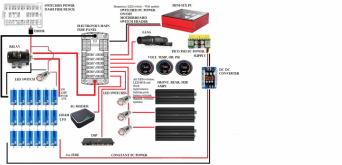
Quick, short thread of an LTO build for car stereo. Not much to it, but wanted to start original thread instead of cluttering up someone else's. May have a few visual clues about process/procedure for others in the future.

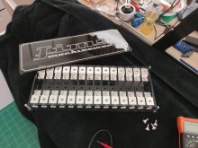
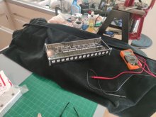
Cells came from Shenzhen, fairly well matched at around 2.28-30v each. 40ah cells, 18 total in this order, boat-shipped to Tampa for $32 each with shipping. Not too bad considering $60/cell if you want them domestically, and you'll be hard-pressed to find them outside the car audio crowd.

Individually charging before passive balancing

IMG_20201013_142501_01.jpg
 
Last edited:
60" aluminum L channel for common rails. Adding to the chain as they finish charging for passive balancing. I'm looking for 14.85v in the end, so doing my best to overshoot the voltage while charging to get them to rest where I need after 12 hours. Voltage does drop slightly, because however low, there is still an internal resistance that brings the cells down a tiny bit before they get comfy.

IMG_20201023_172014.jpg
 
Last edited:
So in my 6S config., I'm looking to charge to 2.475v per cell. With the little psu I have, I've found that maxing out the current, and setting voltage to 2.87v charges a cell up to 2.500v in about two hours at 29.98w (my cell phone quick charger charges at 45w and 5v, just to put things into perspective).

Current maxes out at about 10.33 amps when I attach the leads. I watch the current drop to about 7.35 amps then start frequent checks of the cell voltage. Once I'm at 2.500v, I remove it and throw it on the balance rails. Resting voltage for all cells after 12 hours on the rails is 2.470v, perfect.

I am charging the last two cells a bit higher to bring up the entire parallel bank that 5mV I want in order to get to 2.475v.

I'll be finished charging and balancing tomorrow. I'll pull the terminals and links out and build the entire battery. Then I'll case it in an acrylic case I picked up from LAF:


Should all be finished tomorrow!
 
The supplier I used.


Eliza Cai was my contact. She was great. This order was placed 1 August, 2019. The cells have been sitting untouched in a box on a shelf since then. If you're persistent enough, they are good at negotiating a good deal with you. Wheel and deal.
 
Sneak peek at the acrylic case. Came as a flat pack that I assembled using Acrylic weld. Was a nice kit, very clean. LAF can fab whatever you need as well, just send him your specs. LiFePo4 cells case, LTO, anything acrylic. Great guy.

IMG_20201019_113111.jpg
 
Bummer of a post. Ran into a little snag. The hardware to build the battery won't work. I made this video and sent it to the guy who machined the hardware. Waiting to hear back from him. I misspoke at 1:07 and said 20mm thread engageme3nt when I meant to say 20%.

 
Very interesting!
Why audio?
I was tempted because of cold temperature applications but insulation and a heating pad should keep the LiFePO cells warm. We shall see, the way tech is advancing, everything could change.
 
I need 1.21 jiggawatts to power my stereo, and my flux capacitor is still a few years out.
 
I must be slow, to power your stereo, in a car, a bus, on a moped or home?
Someone must have given you pictures...
 
So the LTO provide backup to the car battery and the alternator?
So, both 280AH LiFePO4 and 120AH LTO or whichever works best?
 
Under-hood battery will be deleted, power distribution center built with 1" acrylic and distro blocks in its place. LTO and LiFePo4 batteries will be installed in the back seat cabin area, all back seat area cleared (back seat components completely removed) and fabbed for amplifiers, DSP, batteries, wiring, fuse block, etc.. LiFePo4 and LTO separated by Tyco 500amp DC contactors with switched ignition.
 
Rudimentary paint diagrams. I have a fan project I'm working on as well. I need manual control of the fans while I demo the stereo while parked to cool the alternator.
 

Attachments

  • PC POWER 2.jpg
    PC POWER 2.jpg
    28.4 KB · Views: 15
  • Master Audio Electrical Circuit Diagram.png
    Master Audio Electrical Circuit Diagram.png
    209.2 KB · Views: 15
  • Master Audio Component Diagram.png
    Master Audio Component Diagram.png
    168.9 KB · Views: 13
  • Main Power Master.png
    Main Power Master.png
    123.4 KB · Views: 14
  • Main Electrical Power Master.png
    Main Electrical Power Master.png
    130.5 KB · Views: 13
And my stock fans are on their way out anyway, hence the integration into the system total design :)
 
Dual Spal 14" fans. Both ECU and manually controlled. Above diagrams do not include LiFePo4, but you get the idea.
 
300a fuses x13, 120a for power distribution to electronic components.
 

Attachments

  • IMG_20201027_152338(1).jpg
    IMG_20201027_152338(1).jpg
    84.9 KB · Views: 22
  • IMG_20201027_152255(1).jpg
    IMG_20201027_152255(1).jpg
    78 KB · Views: 21
Back
Top