Hello everyone,
I've never really experimented with forums and such, so hope I chose the right section of the forum for this topic, apologies in advance if I placed it somewhere wrong.
Using a JK-B2A24S20P for testing and eventually implementing it within a 5kW, later upgraded to 10kW solar system.
I have a situation, with a battery bank of 12S4P, with 237 Ah modules.
Everything is wired according to the diagrams provided, checked and double checked for shorts, and then wired to a Victron Energy, 48V/5000/70A Mutiplus II series inverter.
The BMS balancing leads as well as B+ and B- are wired individually through a 2 AMP fuse.
The BMS turns on without an issue, either from the inverter charging or using a 5V across the P- and B- terminals of the BMS, as I've eventually found out searching through the forums.
Once on, the functionally appears to be normal, showing the status of each cell and the pack together. As well as charge and all the other various bits and bobs.
The charging of the cells works fine without any issue with a constant current of 60A.
The issue arrives when trying to discharge the cells, the 2 AMP fuse that is connected to the BMS B+ and the 12th cell of the pack, blows up the second the inverter turns on to draw power.
Verified the circuit for shorts, multiple times, and by second hands.
Reading through the specsheet/datasheet of the BMS, I couldn't find anything pointing to a large current draw on the B+ terminal, as the BMS should be drawing in the neighborhood of tens of milliamps, which shouldn't blow the fuse.
I also understood that there are some discrepancies in the manuals, are there any updated (Recent) versions of the manual?
Could it happen when it's turning the MOSFETS on, or trying to balance a cell? (All cells showed less than 10mV of total deviation between them).
A friend suggested that the internal resistance of the battery might be at play here, but I'm not sure about that.
Does anyone have any idea what could be causing this?
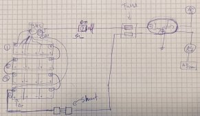
I’ve attached a drawing of the schematic, (The balance leads are not all wired in the schematic but are wired on the BMS unit).
Any info is much appreciated,
Thank you all for the assistance!
I've never really experimented with forums and such, so hope I chose the right section of the forum for this topic, apologies in advance if I placed it somewhere wrong.
Using a JK-B2A24S20P for testing and eventually implementing it within a 5kW, later upgraded to 10kW solar system.
I have a situation, with a battery bank of 12S4P, with 237 Ah modules.
Everything is wired according to the diagrams provided, checked and double checked for shorts, and then wired to a Victron Energy, 48V/5000/70A Mutiplus II series inverter.
The BMS balancing leads as well as B+ and B- are wired individually through a 2 AMP fuse.
The BMS turns on without an issue, either from the inverter charging or using a 5V across the P- and B- terminals of the BMS, as I've eventually found out searching through the forums.
Once on, the functionally appears to be normal, showing the status of each cell and the pack together. As well as charge and all the other various bits and bobs.
The charging of the cells works fine without any issue with a constant current of 60A.
The issue arrives when trying to discharge the cells, the 2 AMP fuse that is connected to the BMS B+ and the 12th cell of the pack, blows up the second the inverter turns on to draw power.
Verified the circuit for shorts, multiple times, and by second hands.
Reading through the specsheet/datasheet of the BMS, I couldn't find anything pointing to a large current draw on the B+ terminal, as the BMS should be drawing in the neighborhood of tens of milliamps, which shouldn't blow the fuse.
I also understood that there are some discrepancies in the manuals, are there any updated (Recent) versions of the manual?
Could it happen when it's turning the MOSFETS on, or trying to balance a cell? (All cells showed less than 10mV of total deviation between them).
A friend suggested that the internal resistance of the battery might be at play here, but I'm not sure about that.
Does anyone have any idea what could be causing this?
I’ve attached a drawing of the schematic, (The balance leads are not all wired in the schematic but are wired on the BMS unit).
Any info is much appreciated,
Thank you all for the assistance!