diy solar

diy solar

Jk bms overvoltage protection on one cell imbalanced

@Steve_S what is bad with having fuses on balance leads?
Besides being fairly pointless, the added resistance won't do anything favours, generally it causes more problems. The notion comes from the EV world partly, but what far too many don't grasp, is that with EV's the BMS Systems are designed specifically for fusible links etc and account for that in the tolerances. All lithium Cells are Millivolt/Milliamp sensitive and that is NOT a game to play loosy goosey with.

With a current STD JK, on a 8s/16s pack, cell resistances should be between 45-55Ω preferably 49-50-51 when properly done. Even silver soldering the terminals will change that value, but they should be as close as possible.

Sadly, sometimes what may seem like a good idea is just one step too far and has the opposite effect...
Wouldn't you have to weigh that against the risk of a balance lead shorting and heating up, potentially having a cascading effect if the balance leads are bundled together?
 
Wouldn't you have to weigh that against the risk of a balance lead shorting and heating up, potentially having a cascading effect if the balance leads are bundled together?
Have we ever seen a documented case of this type of failure ?
 
I can count on 1 hand with fingers left over at how many times Balance leads failed & caused issues. That one GSL/Edisson mess is a GSL Design Flaw with cells being on their sides (talk about IDIOTIC) that leaked corrosive electrolyte onto the wires etc...

You are getting caught up in Minutia and likely driven by the FUD flying around the web...

WIRE MANAGEMENT regardless of what it's in needs to be done. There are many solutions that work in the various cases/boxes & DIY enclosures. Wire Looms, to PVC channels and many more can do the job.
 
I can see pro’s and cons in fusing the balance leads so laziness was the deciding factor not to.
 
Now I replaced these 5 fuse holder and clamp by soldering and shrink. Resistance between 65 and 85.
Cell voltage still 0.020 lower if I check it on the cell with a multimeter in compare to the bms.
So i currently not able to charge until 100%.
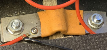
Sense cable are connected not directly to the + connecter but to the small m5 of the + side of the Busbar. If I place the sense cable manually directly to the positive connector, it shows me up the same wire resistance in the bms.

I plan to buy new balance cable and go for a connection without a fuse.
 

Attachments

  • FE077AAC-DCBC-43B8-9322-2134EEBB9D1C.jpeg
    FE077AAC-DCBC-43B8-9322-2134EEBB9D1C.jpeg
    506 KB · Views: 3
Wouldn't you have to weigh that against the risk of a balance lead shorting and heating up, potentially having a cascading effect if the balance leads are bundled together?
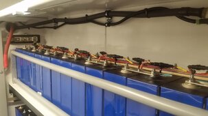
Batrium uses fuses on the leads. It took me some time to run all these on 64 cells.


Balancing leads.jpg
 
Ok, so you not wire the sense cable directly to the pole and use the
Fuse holder I just remove to find the source of my different wire resistance.
What wire resistance did you have? Are the values per cell is the same in bms and multimeter?
 
Back
Top