diy solar

diy solar

Jk bms overvoltage protection on one cell imbalanced

Christian_on_Tour

New Member
Joined
Jan 1, 2024
Messages
9
Location
Truck
.
Just wired up a 2x 16s 280ah 3.2v/cell 16-cell "48v" EVE LF280K LiFePO4 battery banks with jk bms

One cell in each bank keeps going over voltage 6 and 16.

I swap cell 6 with a cell from the other bank to see if I have an cell issue, no success.
General charging set to 2 A prevent a fast cut of.

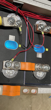
For my Setup I did some research and so I cut the sense cables by half, add a clamp and after that a 10cm cable with a holder for a 5 A Glas fuse.
Sense cable are connected to the flexible bus bar positive side (m4 screw) and not directly to the nut.
 
Last edited:
It sounds like either:
1. You didn’t top balance your cells. In that case your described behavior is exactly what would be expected. One cell get full first and its voltage increases and triggers OVP.
OR
2. Your BMS is getting bad voltage readings. I don’t have a clue what your second-last paragraph means, but adding a bunch of items between the cells and the BMS might be causing some bad readings. You should verify with a Multimeter that your BMS cell voltages are representative of what you measure at the cell terminals.
 
Reduce charging voltage to the point it is below the high cell cut off. With 48v I would add a NEEY active balancer and let it work a few weeks while the battery is in service. Then increase the charging voltage assuming the runners have been put down.
 
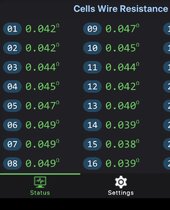
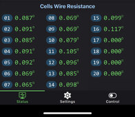
What does your “Cell wire resistance” reading look like. The cells that are furthest from the bms should be a tad higher. If you have runners, you got a problem. Example of a good system;
IMG_1207.jpeg
 
94EF9254-049E-4CCC-93ED-A955EA4285F5.jpeg- Cell wire resistance (image)
- Average cell volt 3.377
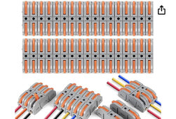
- Cables I put between as I want to avoid
soldering (image)
- clamp (image)

I will add later some more pictures when the sun comes out and I get daylight.
Initial balancing was done over 2 weeks around with 16 in a row and charging until the Amps of the charger went to 0.
Then the cells wasn’t used for 2 month.
 

Attachments

  • 335E9F08-CB91-446C-B4C3-40F4F99F100B.jpeg
    335E9F08-CB91-446C-B4C3-40F4F99F100B.jpeg
    332.5 KB · Views: 13
  • 36396F8A-D17E-4854-B45B-9D3FCBC012E2.jpeg
    36396F8A-D17E-4854-B45B-9D3FCBC012E2.jpeg
    218.2 KB · Views: 11
  • C66D91AF-4E24-4BDB-AA07-DFF273D43BEC.jpeg
    C66D91AF-4E24-4BDB-AA07-DFF273D43BEC.jpeg
    682.2 KB · Views: 10
It sounds like either:
1. You didn’t top balance your cells. In that case your described behavior is exactly what would be expected. One cell get full first and its voltage increases and triggers OVP.
OR
2. Your BMS is getting bad voltage readings. I don’t have a clue what your second-last paragraph means, but adding a bunch of items between the cells and the BMS might be causing some bad readings. You should verify with a Multimeter that your BMS cell voltages are representative of what you measure at the cell terminals.
How can I adjust point 1. now? Remove all cells and put in a row to charge?
 
I swap cell 6 with a cell from the other bank to see if I have an cell issue, no success.
Along these lines, ideally you would have your 16 strongest cells in one battery and your 16 weakest in the other.

Capacity testing takes weeks upon weeks. But if you can do some charge cycles you may be able to identify the runners (weakest) and get them with similarly low capacity cells.
 
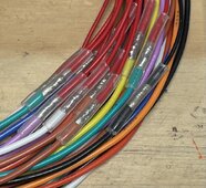
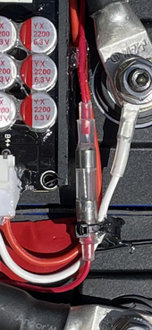
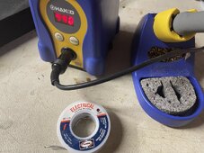
Look at your cell resistance. One cell below the highest and lowest (resistance) are your worst cell voltages. I don’t think that’s a coincidence. All my batteries are within.012 difference, yours are .052. Those fuse holders are a nightmare for intermittent connections. Brass contacts to nickel fuse ends are a problem especially with time and moisture. Personally I’d not use the fuses and blocks. Nothing wrong with soldering and heat shrinking small leads if done right. Stable heat, clean and (leaded) 60/40 rosin core.IMG_1174.jpegIMG_1027.pngIMG_1210.jpeg
 
Last edited:
First:
A few words about JK default settings: generally the JK default settings are crap for LiFePO4, you need to adjust these (if you haven't already) IIRC the default high cell voltage disconnect setting in the JK is 4.2volts - far too high - should be 3.65volts. Check all the BMS settings before you get into the running cell issue.
Second:
If you didn't attempt to top balance the cells prior to building the pack, the couple cells out of sync with the others is rather expected.
Before pulling the whole works apart, I would suggesst taking one pack out of service, and pull the one one cell voltage down using an automotive bulb attached just across pos/neg of that one cell. - yes you can do this with the rest of the pack left as is. I use an auto headlight bulb for high current draw.
It is best to do this with the pack near high SOC, or at least as high as you were able to get when the JK BMS interrupted charging due to the one high-cell-voltage (over-voltage).
You can use your phone to monitor the JK cell voltages and watch that one cell voltage drop while the others remain unchanged. If the problem cell is "way higher" say 3.65v while all the others are 3.30, then you will want to pull the offending cell voltage down close to 3.30, then charge the whole pack up - attempting to get all the cells to fill together to 3.65v each. Likely your runner will still be a runner as you charge and you will need to repeat the process of charging until high cell voltage cut off, pull the one cell down with the bulb trick, repeat.
Also to note: rebound. If you pull the voltage down on one cell for 20-minutes, and then disconnect that bulb, leave everything for a few minutes and watch the cell voltages on your phone-app. You will see the cell voltage creap up after removal of the load (bulb) - this is normal, and shows you may need to pull the cell voltage down 'extra' say to 3.28 if you want it to rebound to 3.30 for example.
Sorry for the long-winded explaination, hope this helps.
 
Check the balance start voltage. It should be above 3.4 I like 3.43. If it was sitting around for a while and the balance was active below the knee, a few milivolts correction where it doesn’t need it can make a mess at the top.
 
If it was sitting around for a while
Just wired up a 2x 16s 280ah 3.2v/cell 16-cell
posted yesterday. I don't think the JK is even starting the balancing, OP is getting a high cell voltage disconnect before the low cells are high enough to even start balance - not enough info posted to confirm.
With the cell-votages too-far out of balance nothing is going to fix this because the BMS will shut down charging before it ever starts balancing.
 
We are looking at 10's of mv here, anything that could add resistance will.
Direct, short as possible within reason and same length balance wires are the only way to go.
 
WOW... just caught up on this....
So much not right here...
DON'T MESS with the balance Cables !!! Fuses etc = BAD in there...
All Lithium IS Millivolt/Milliohm Sensitive !
Wire Resistance should be between 0.045 - 0.055 when it is good and they should all closely match. When they don't ISSUES HAPPEN !
JK Defaults for LFP are NASTY ! Quite wrong... This has been corrected in the new Inverter Models.

Corrected JK settings for LFP
1668722069256-jpeg.120672


<- Can be no higher than 3.650

<- 75mv recovery difference is most flexible.

<- Prevents bricking BMS Recovery Voltage.

<-- Undervolt safety - see above.

<-- Power off while keeping enough to prevent BMS shutdown & bricking.

!!! START BALANCE ! Start @ 3.42, Most Optimal to allow the cells to fill & top out.


<--- Depends on BMS model & cells used. Remember charging @ Max 0.5C


<-- again depends on BMS & Cells.


** CRITICAL ! TEMP DEFAULTS WRONG !!!
<--

<--

<--

<--

<--

<---- end of adjustable temps.


CHARGE PROFILE SETTINGS that work without stressing any cells etc.
All equipment MUST BE Voltage Corrected & Calibrated (VERY IMPORTANT)
Divide Values X2 for 12V. Multiply X2 for 48V.

Bulk - Absorb: 27.6V (3.45vpc) (some call this boost) *Absorb for 45 Minutes, but never actually runs the full 45mins because of EndAmps
Equalize: OFF
Float 27.5V (3.437vpc) (Constant Voltage - Variable Current)
MIn Volts: 21.2v (2.650vpc)
Max Volts: 28.6v (3.575vpc)
Rebulk Voltage: 25.6v (3.200vpc)
End Amps/TailCurrent : (*1)(* Allows for full Saturation at set Float Voltage)
(*1): End Amps is calculated IE: (100AH X 0.05 = 5A OR 280AH X 0.05 = 14A.)
EndAmps = TailCurrent. This is what Transitions from ABSORB to Float to finish off the last 5-7% of the charging.
Coulumbic Efficiency / Battery Status Meter Efficiency for LFP = 99%.

REMEBER to Correct & Adjust your equipment. Test the voltage at Battery Terminals and at SCC & Inverter... Adjust to correct for any losses.
 
Steve, if that’s your running bms values, double check your start balance voltage. I need my reading glasses just so I can see mine. I need to revisit my battery temp settings when I get home myself to double check. I can’t remember if I changed them.
 
Hi, thanks for all that input, my next step will be remove the clmp connector and replace with soldering 5a fuses to replace also these fuse holder.

One bank of the 2 looks now better after checking all connections but the other bank has now wrong cell reading between BMS and multimeter.

So i will order transparent Heat shrinks now and go ahead with bank one and then 2.
 
Look at your cell resistance. One cell below the highest and lowest (resistance) are your worst cell voltages. I don’t think that’s a coincidence. All my batteries are within.012 difference, yours are .052. Those fuse holders are a nightmare for intermittent connections. Brass contacts to nickel fuse ends are a problem especially with time and moisture. Personally I’d not use the fuses and blocks. Nothing wrong with soldering and heat shrinking small leads if done right. Stable heat, clean and (leaded) 60/40 rosin core.View attachment 186403View attachment 186405View attachment 186411
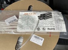
Is It a common heat shrink that you used for the fuse?
 
Steve, if that’s your running bms values, double check your start balance voltage. I need my reading glasses just so I can see mine. I need to revisit my battery temp settings when I get home myself to double check. I can’t remember if I changed them.
The JK Settings screen I posted is older... I have since changed to 3.42 Volts to start Active Balancing and found that to be the "Sweet Spot" as I only charge to 27.6V (3.450Vpc) and Float @ 27.4V (3.425Vpc) I tinkered with the settings while observing the 6 BMS' and tweaked that to my setup. Now as my setup will be changing drastically in the next couple of months, I will end up redoing all my tests & tweaks. Changing all of my current JKBMS fleet to the new JK Inverter Edition and reconfig of bank so it will be 6 Steel Cased 280AH Packs. I already gave away the 2x 174AH's and my 105AH is headed to the toolshed.
 
Is It a common heat shrink that you used for the fuse?
I use this stuff; https://a.co/d/6kdHLmg

1/8” for the small 22AWG wire and cover the non insulated terminal barrels. It is reasonably flexible and is a nice strain relief and is clear enough to read numbers on see the fuse filament. On 5X20 mm fuses I’d use 1/8” on each wire and 3/16” to cover the body, that way you don’t overheat the shrink tube ito get contact with the small wire. I don’t trust those fuses until I’ve sacrificed a few with a power supply from the same lot. “IF” I were to use a fuse I my balance leads if be sure that they have all the same resistance, probably use an internal resistance meter just for giggles. You don’t want to spend much time soldering on the fuse. 60/40 melts sooner than the eco RoHS crap. Tin a low button on each fuse end, tin the wires, then solder the assembly. Be quick.
IMG_1211.jpegIMG_1212.png
 
Back
Top