diy solar

diy solar

A couple questions for Epever experts.

D

Deleted member 783

Guest
I just received the Epever 60 amp model. Two questions:

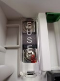
1. It has an internal fuse that is not labeled. Can I assume it is a 60 amp fuse? Anyone know where I can find one?

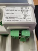
2. It does not have "load" out (12v) like I am used to seeing on charge controllers. There is, however, a "load relay", but zero instructions on how to use it. Anyone?
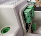
20191211_083052.jpg20191211_083402.jpg20191211_083420.jpg
 
The 'load' port is designed to output low current, enough to trip a relay, based on the programmable triggers in the EPever. I'm thinking it will be at whatever voltage the battery bank is set to. That relay can be used to trip anything you want, so there is virtually no limit on the 'load' the EPever can handle. I would think the specs and usage would be in the manual. If not, contact EPever.
 
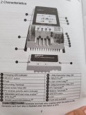
I dont get it. Why is it wired to the inverter? I was hoping to draw 12 volt power from it. The ONLY mention of the load relay in the manual is where its listed as existing in this diagram.

20191211_144937.jpg
 
No. It's not a power load terminal. It only exists to be connected to an external relay, but can still be controlled by the internal timers.

It is not at all like the load terminals on the lower amp units.

Gotcha. I don't understand what to use it for. I emailed epever so maybe they will send me soething.
 
Think of the relay as a switch. The epever throws the switch. Epever does not know what type of switch you need so they make it easy to add whatever external switch (relay) you need based on your load. If they built it inside of the epever you would (sort of) be stuck with whatever switch (relay) they guessed most of their customers would need. Keep the cost down by including a lower rated relay and make things more complicated and costly for those who need to control a bigger load. Include a higher rated relay an you needlessly add expense to customers who don't need to switch a higher load.
 
I don't understand what to use it for.
You can use it for anything you had already planned on using it for. The only difference is that the relay has been moved from an internal version to an external version that you supply. Allows for a much greater flexibility of connected devices.
 
Does that trigger still have the timer, dusk-dawn and duration control to an external relay like the smaller CC? If so that would be so much more usable and allow more power for other things.
 
Ok I found one answer online:

Hi, the tracern AN series 50A/60A/80A/100A, doesn't have load terminals. If you are using a power inverter, you can use the relay to send signal so as to turn on /off the inverter automatically if battery voltage below a setting value.
 
I still have no clue how I am supposed to use this for 12 volt power without tapping it from the battery.
 
Does that trigger still have the timer, dusk-dawn and duration control to an external relay like the smaller CC? If so that would be so much more usable and allow more power for other things.

No clue. It's not mentioned at all in the manual.
 
Yeah I to interested in how to wire that connection to a relay and also wiring for a remote generator start.
The MPP 812 all in one I had also had the similar generator connection to remote start a genny if no grid was available. Maybe someone could draw a simple wiring schematic that us amateurs sparkys could savy?
Always trying to learn but as an ole concrete mixer driver wiring can boggle the mind. I left that vast tangle of control wiring on the mixer to the wrenches. LOL
Some schematics look like tangled spaghetti noodles to noobs. ?
 
Last edited:
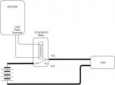
Can't get much simpler than this....
The load can be as much as your battery and relay are designed for, could be hundreds of amps. The input voltage of the relay needs to match the output voltage of the EPever load relay terminals. I just drew it with the N/C (normally closed) being used, but you would use whatever suits your application. The battery charge output of the EPever would also be tied to the battery (not drawn in).

relay.jpg
 
I should also mention that this could also be used on a charge controller that has 'standard' load terminals. Just attach the relay to the load terminals just like above. The 'load' to the charge controller is the relay itself, very low wattage. The relay in turn could drive hundreds of amps, even if your charge controller is a 10 amp unit, but probably not practical in real world scenarios. If the CC was only a 10A unit, it couldn't replenish the batteries drawing very high current loads.
 
Why is it wired to the inverter?
Ok, I just re-read that and looked more closely at the diagram I posted first. That's EPever's inverter. It not only has DC inputs and AC outputs, it also has a separate connection to tie back to the charge controller's load relay terminals. In that config, the charge controller can turn the inverter on and off based on internal timers/triggers.

That said, maybe my diagram of a generic external relay should be taken with a grain of salt, might not be a supported config.
 
Thanks Rider! Even if your digram is correct, it's still pulling load directly from the battery, correct?

I think the best way for me to get what I want, which is 12v water heating, is to run a separate system with an old charge controller.
 
I have a post on how to parallel these controllers using the PT-ADP-PORT....

 
Back
Top