diy solar

diy solar

AC coupling - Maximum distance between inverters?

lapsmith

New Member
Joined
Apr 10, 2022
Messages
234
I searched this site and couldn't find an answer to this question. I also looked at some inverter installation manuals.

My solar array and grid tie inverter would be about 300 feet away from the inverter and batteries in the garage (house). This works best for my situation due to lots of trees close to the house and the fact that the main utility line already runs from the location where the arrays would be to the house. There is also a breaker panel there.

Thanks,
Tom
 
AC coupled inverters can be any distance of AC wire, so long as voltage drop (or rise) doesn't go beyond the grid limits set in the inverter.

Main problem is likely to be utility is sending 250V to your house (to make up for drop when loads are applied), but your PV is pushing voltage even higher.

You might be able to game that by widening voltage limits in inverter settings (not supposed to do that, and requires installer access), or use a buck-boost transformer to shift the voltage.

I recommend instead using long PV DC runs, if possible. My 600Voc inverters are connected to 480 Voc, 380 Vmp PV strings. Higher voltage, lower loss than 240Vrms AC, and voltage drop doesn't matter much, no tight limits for PV like there is for AC.

Since you've already got an AC wire, examine to determine wire gauge and look up resistance. Test by measuring unloaded voltage, then connect loads like space heaters and measure voltage. Whatever voltage drop you see, calculate instead if it was voltage rise. Determine if that would exceed max and cause inverter to disconnect.
 
Thanks Hedges. Makes sense that there has to be a slight voltage difference between the inverter and the grid. You were right...I measured the voltage at the meter (where the solar panels and inverter would be) and it is 253. It is also 253 at the house (approx. 300 feet away), but that's with minimal loads. I will pull the service panel to see what size wire they ran, but I'm hopeful it is oversized because there is a 400 amp disconnect just after the meter and before it goes to the house. That thing is huge.

The problem with running DC is not just the distance, but also that there is a creek I would need to cross so that would really complicate things.

I will also run a test with loads to see what kind of voltage drop there is.
 
Voltage is 5.4% high, will go higher depending on resistance of the 300' run. If sized for 400A (!), maybe not much. But doesn't take much to exceed limits.

Would rather fix that with changed limits in inverter, but that may not be possible.
The inverter possibly can be configured to drive current out of phase (like the Volts-Var function) which reduces voltage rise.

What may be easiest is to change AC voltage seen by inverter with hardware.

There are 120/240V to 12/24V buck-boost transformers that could take in 240V and add or subtract 12V to that. But if inverter requires neutral connection and objects to excessive offset in voltage, same transformer would have to be used to make each phase 126.5V - 12.65V, which may be too low when utility line voltage sags.


Using two, primary wired for 240V but fed a single 120V leg, the "12V" output would be 6V, so 120V - 6V = 114V or 126.5V - 6.3V = 120.2V

Expensive at Graingers, but you can find surplus transformers on eBay. Just need one with 6V or 12V secondary rated to carry the current of the inverter.

I used an autotransformer configuration to create 277/480Y for a 3-phase inverter from 120/208Y. Was actually getting 125V not 120V from grid. The inverter saw excess line voltage, at least when delivering a quite small amount of power. I had to change to a transformer ratio that aimed for lower voltage. Yours might connect initially, then disconnect as soon as their output made voltage rise. The Volt-Var function, if available, could help.

Transformers have a significant voltage sag, or rise in the case of being backfed. Higher wattage (VA) rated transformer will have less sag for a given wattage load.
 
I did a load test and with a 5.5kw load, the voltage went from 253 to 252.5. I also tried to see what size wire it is that runs from the 400A disconnect to the house (it is buried). Unfortunately, the exposed wire that I can see doesn't have the markings visible. But there is this datapoint:

After the 300 foot run, there is a junction box on the side of the house where there is a splice. The wire coming from the 400A disconnect is spliced to a 2/0 wire which goes inside the house to the main breaker panel and another 2/0 wire which goes back underground and to the barn about 75 feet away. The 2/0 aluminum wire is .615"OD (including insulation) and the heavier wire is .875OD. So I'm guessing it is maybe 4/0 or 250?.

So I guess I will look for an inverter that can put out a higher voltage. I'd rather do that than add more equipment, wiring and expense of transformers. If it gets that complicated, then solar loses its appeal. Using two transformers would be the way to go, but it gets even more expensive. Unfortunately, data on inverters is not readily available. I looked at the Sonny boy and couldn't find anything on line. I also discovered that SMA doesn't sell direct, it looks like I have to be an installer to buy.

Back to basics, I'm surprised this is even an issue. I would think most homes see more than 240V with no load.

My other option is to locate the solar array elsewhere, but then I have the expense of cutting down a bunch of trees (one estimate was $10k). Plus I hate to lose the trees. Not so simple!
 
Wow, that's great news! I was so bummed my plan might not work. I have a lot more details to work out, but I think that was the biggest concern. They tout their ShadeFix technology. Does your have that and does it seem to work, or is it more of a gimmick?

Also, it seems that model line has been discontinued. Now I have to look for something similar.

Thanks so much for your expertise and guidance!
 
Shadefix - MPPT full voltage sweep by any other name. Each company has its algorithms, and some fail move beyond local maxima to find highest power peak.

Power optimizer might work for some people. I would prefer to plan where any shade falls, try to have it hit multiple parallel strings similarly. But the newer inverters have multiple MPPT, so each partially shaded string has no effect on others. Bypass diodes should be all you need. Unless you're required to have RSD.

Are you backfeeding the grid? If so, need an inverter with whatever features are required. I discovered that California's CEC website had only some features displayed. Have to download spreadsheet to get additional columns with the ones required since mid 2020.

You may find SB -41 inverters still for sale. Being replaced with SBSE (adds a battery input) available in January.

If no particular features required (because not on grid), then old models work too.
You of course receive grid voltage. Will these be net metering? Zero export? Behind a battery inverter (as implied by "AC Coupling")?

You might for instance set up Sunny Island between grid and Sunny Boy, and tell it to disconnect from grid whenever PV production exceeds loads including battery charging.
 
Yes, I will try to have a few parallel strings and would love to have an inverter with multiple MPPT inputs, but I also have to ensure the inverter with that feature can output the needed voltage.

I am considering back feeding the grid, but my neighbor (I'm in the Houston area) says the providers pay very little, so it may not be worth the hassle. I haven't asked, but I think Zero export would be the easiest.

I'm not sure I will be behind a battery inverter. My battery inverter would be in the house (garage) which is downstream of the grid tie inverter. But technically, they are in parallel, right?

I did see a SB US-41 inverter on Ebay, but there would be no warranty and it was only 5KW. The SBSE models are more expensive and come with features I couldn't use since I will need another inverter near the batteries anyway.

I like your suggestion of the Sunny Island and Sunny boy then disconnect if power exceeds demand, especially if that is just a selectable setting. I'm assuming there is no load shedding needed if the solar array is putting out more than demand?
 
Grid feeds Sunny Island. Output of Sunny Island feeds Sunny Boy, also any protected loads. So not in parallel (except there wattage combine in parallel off grid), and the battery inverter can't be downstream of the PV inverter.

Zero export with just Sunny Boy, I haven't done it or figured out exactly which equipment. I think a power meter with CT and a controller which reads that and talks SpeedWire to inverter. It is a system SMA offered for Hawaii, etc.

No dump load (or shunt regulator) necessary if PV generates more than needed. SI does frequency shift and SB curtails. But you can use a signal to enable a dump load like water heater.

Load shed is recommended if battery gets too low, keep island grid with critical loads and Sunny Boys powered, but disconnect heavy loads.

Load dump is when a load turns off. SB keep delivering power for a couple seconds until frequency shift occurs, and SI shoves that into battery. Need enough headroom so BMS doesn't disconnect for high cell voltage. DC coupled PV doesn't have that problem because MPPT charger sees battery voltage directly.

If the price is right, no warranty needed for Sunny Boys. They are reliable. Just want assurance that it won't be DOA. So far all I've bought were working, even listed "for parts or repair" because seller received a donation and couldn't test.
 
I can't have the grid feed Sunny Island then Sunny Island feeding Sunny Boy because I'm using the 300 feet of buried service line to AC couple the two inverters. That's why I thought they would be considered in parallel. In other words, they are both connected directly to the grid, just that one is close to the PV array and one is 300 feet away at the house with the batteries and loads. Or at least, that's the way I envisioned AC coupling...but maybe I'm missing something.

Sorry, I used the wrong term. I meant load dump. Since I plan to go with Lithium batteries, if the BMS disconnects due to high voltage, does anything get damaged? And where does all that energy go that the cells are producing? I have an electric water heater so that would be an ideal dump site, but do inverters typically have a connection for something like that, or do I have to do it externally some how?

Sorry for all the newbie questions!

Good to know about buying used Sunny Boys. I will keep an eye out.
 
You could install Sunny Island anywhere between Sunny Boy and the utility meter. Including 300' away from Sunny Boy.

2x SI stacked for 120/240V split phase would only pass 56A through.
4x SI could pass 112A through, or close (parallel paths can't be counted on to balance perfectly.)

One member found someone with dozens of SB 6000US that were hung but never commissioned. The asking price was something like $780 for one, but discounted for quantity. Location is Texas. Shipping a pallet is probably several hundred these days, but you can stack several inverters on one pallet.
 
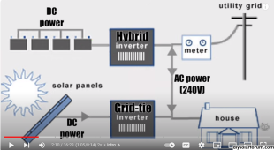
Would it look like this? I got that schematic from a Farmcraft video.

Oh wow, I will look for that post that since I'm also in Texas. Where are you located, out of curiosity?
 

Attachments

  • 1699489361381.png
    1699489361381.png
    276.5 KB · Views: 0
Here ya go:


I'm in San Jose.

I bought a pallet of SB 5000US a couple years ago for $500 apiece including shipping. Considering destruction of dollar, with a quantity discount, the deal above should be similar.

Block diagram in data sheet:


The newer inverters have Rule-21 frequency-watts, which should work.
Older models have UL-1741 with anti-islanding, and do frequency watts in off-grid island mode. Per written instructions, you're supposed to have SB in UL-1741 mode when downstream of SI and grid connected. Run RS-485 wire from master SI to all SB (each with daughter card) for backup operation, so it dynamically switches modes.

Only supposed to use Island mode if strictly off-grid.

RS-485 good for 1200m

 
Thanks for the link. They are only 2 1/2 hours away so a good deal for sure. One question though. In the SI block diagram, the position of my SB's and SI's would be reversed. I.e. the SB's and PV would be closer to the grid than the SI's and batteries. Would that make any difference? Is that what you mean by they have to be in UL-1741 mode?

I wonder why they weigh so much. Do they use transformers or have more copper than newer models?

And while the SB's are a good deal, I would need two SI's and I see that they aren't cheap. OTOH, I like that they have a good reputation for reliability.

Good to know that RS-485 is good for 1200m. I had looked up Cat5 maximums and it was 100m. But that's probably apples and oranges. I can manage running that kind of wire 300 feet, even across the creek.

When you say Only supposed to use Island mode if strictly off-grid, do you mean totally off grid, or just when the grid is down?

I have to run out now, but will read all those data sheets later. I'm guessing the "Speedwire" is also RS 485.
 
When the grid does down, anything attached to the grid has no power.

Sunny Island is a UPS. You connect a battery to it, and battery is charged from the grid AC2 input terminals. If grid goes down, SI disconnects by relay and makes power downstream, AC1 terminal "island" grid. If Sunny Boy is connected to AC1, it's power can also charge battery, and you have an AC coupled offgrid system. When grid is up, SB can backfeed grid, or not, depending on SI configuration (disconnect from grid to prevent backfeed.)

If SB is connected directly to grid wires (same as SI AC2 terminals), it can't supply SI when grid is down. When grid is up, it can supply all loads on the grid side, SI, and all loads on SI AC1 side, also backfeed the grid. If you want zero export, you need a configuration with CT going to a meter, and a controller that commands SB wattage. I don't know the details.

You want SI installed upstream of SB. That makes a grid-backup system that runs indefinitely. If loads are large enough to drain battery, you should run 48V control wires from SI to power relays, thermostat, etc. for load-shed.


SI and these old SB have copper wound low-frequency transformer, so they are isolated from the grid. SMA pioneered transformerless grid-tied inverters and received utility permission for them. Those are the models with "TL" in the part number. Also Sunny Boy Storage battery inverter (but it requires transformer to make 120/240V split phase.)

Ethernet may be 10 Mbit to 100 Mbit on Cat5, with magnetic isolation in RJ-45 jacks. Speedwire is Ethernet, can connect through router to your PC or the web.

You could use Cat5 cable for RS-485. RS-485 may be 1200 baud to 19,200 baud, non-isolated, and SMA equipment defaults to 1200 baud.


2x SI is good to buy. If you were paying $5750 msrp or $4750 street price, you could consider a transformer to make split phase, but with the DC Solar bankruptcy liquidation making these available between $1200 an $2500, buy two. It makes a very capable system. AC coupled with SB, you get available PV watts carrying loads, and 2x SI can then deliver 22kW surge for 240V motor starting (11kW for 120V). SB and SI wattage add together when the sun shines. You can put 24kW of SB on 12kW of SI, if not backfeeding, or 13.4kW SB if backfeeding (relay limit 56A).

Totally offgrid, so they can never find themselves looking into the grid and not performing anti-islanding. To comply with regulations and manufacturer's instructions.

The older SB with RS-485 can switch between UL-1741 (with anti-islanding and grid voltage/frequency limits), and Island (wide limits, no anti-islanding.) That is called Backup. According to documentation, you're supposed to use Backup mode for SB that is downstream of SI, when SI is fed by grid. Other brand GT PV, and newer SB without Backup, you're supposed to use Rule-21 (has anti-island, frequency-watts, and slightly wider voltage limits.)

It does function just fine under normal circumstances to configure any SB for Island and use downstream of SI for grid-backup. SMA support told me to do that after I bought SB 10000TL-US-12 and discovered Backup failed to implement frequency-watts. I saw a video from SMA America saying to put SB -41 in Island mode for systems like that. Yet written instructions from SMA Germany said not to. I suspect it is due to FMEA, they realized that if relay in SI welded shut, they would have GT PV inverter stuck on the grid and not performing anti-islanding. We do hear of these relays welding. I would guess SI can tell when relay is stuck, and would therefore not tell SB to switch from UL-1741 to Island. I was not comfortable with it so I took down my 10000TL-US and replaced them with SB 5000US, which do have a correct Backup mode.
 
If you run a data wire, include enough pairs for anything you might want to control.

RS-485 has a twisted pair Data +/- & ground, 3 wires.

Each SI has two SPDT signal relays good for AC or DC, also PTC fused Bat +/-
Using a twisted pair for power plus return to relay would minimize coupled interference, but that's only during a moment of switching anyway.

The relay functions include generator start (need external transfer switch if you have both relay and grid),
battery fan,
Load shed (two SoC levels)
Dump load,
"on grid",
many others.

If you use a transfer switch for generator, a dry contact can tell a SI through its digital input, so zero backfeed and different current draw, also warm-up & cool down are implemented.

If you use DC coil contactors for high power loads, look for one with "economizer" to minimize power consumed by coil.
 
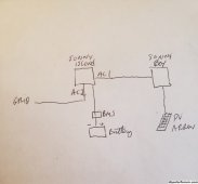
I understand the configuration now that you are describing. It looks roughly like this if I'm not mistaken:

Sunny config 20231109_154138_resized.jpg

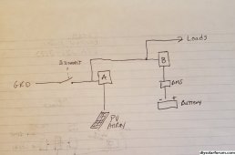
Unfortunately, I can't use that arrangement. I need to have the solar arrays and their inverter upstream of the batteries and their inverter. Something like this:
My needed config.jpg

I don't know if that is possible with the SB/SI, or in fact any inverters. I'm assuming I would need a disconnect so I don't back feed the grid, assuming the inverter doesn't have that capability.

In the figure above, A would be a grid tie inverter and B would be a UPS or possibly off-grid inverter, if that makes sense.
 
As you've drawn it, "B" doesn't have any loads. It will charge it battery, not do anything else.
You could attach protected loads to it.

Why can't you put battery inverter at the location where you show Disconnect?

Inverter/chargers have an internal disconnect, so they can drive their output without backfeeding the grid.
It would be possible to have a system where the disconnect was external and remote, upstream as you show. But that may not be a readily available product.
 
Sorry, yes, inverter B would have critical loads. Not sure what you mean by protected loads.

I can't put the battery inverter at the location where the disconnect is because that is 300 feet away from the house where the loads are. So I'd have to run another AC line to the house for the critical loads. Or is there another way?

I was wondering about the internal disconnects on inverters. In my case, I have 400 amp service going to the house. I didn't think I could pass that much current through an inverter. And judging by the size of the 400 amp manual disconnect, a similar sized relay (controlled by the inverter, assuming there is such a thing) would be huge and prohibitively expensive.
 
Back
Top