diy solar

diy solar

AC coupling - Maximum distance between inverters?

Critical loads meaning keep them powered to the last gasp of the battery. Includes Sunny Boy, since they need AC in order to deliver PV power for charging. Alternatively, you can tell Sunny Island to sleep until an alarm clock goes off. Or search mode, I think, where it periodically wakes up to check for loads - not sure about that one.

By protected loads I mean same as critical loads, except have a relay to shed them at say 70% DoD (at least with lead-acid, SI keeps operating down to 80% DoD, using 10% to keep critical loads and SB powered.) For HVAC, you'd only have to control the low voltage thermostat signal.

If you run the battery down to the point of SI shutting off, it won't pass grid through and it won't wake up. If that happens you need a way to recharge the 48V battery. Then when it is awake you need to reduce AC loads below the power produced by PV so battery continues to charge. Load shed is supposed to take care of this.

You don't need another AC line to the house if you use the existing AC wires to power the house. That makes all loads critical loads. If you split the wires to two sub panels, and use a load shed relay for one of them, then you have separate protected loads and critical loads. Need a pair of wires e.g. doorbell or LAN wire to switch the relay. I use a 48V coil relay that is listed in SI manual as accessory. Could use 120V or 240V coil relay, wired with suitable insulation.

Of course, this limits you to 56A 120/240V for all loads. I use 4x SI stacked 2p2s for up to 112A feed through.

400A or 200A relays are much smaller than safety switches, about the size of breakers. SMA has a 200A relay in an external box for other products but not US model Sunny Island. They used to offer one together with auto-transformer for a single Sunny Island, haven't seen it in years. They have 200A relay for US model Sunny Boy Storage and European model Sunny Island.

Do you use all 400A? Or just 200A?
You could set up a transfer switch, or interlocked breakers in 200A panel, located where you show disconnect switch. While grid is up, 2x SI are fed (AC2 input) from a 70A or smaller breaker, keeping battery charged. If grid goes down you manually shut off excessive loads, manually transfer from grid to SI AC1 output. (switch off AC2 input if fed from same panel so SI input doesn't see SI output.) You are then running off grid.

If you feed SI AC2 input from fused or breaker protected input of transfer switch, then grid is available to keep feeding SI and loads, and PV can still backfeed. This is what I've got - 200A breaker at meter branches to 200A loads panel and Sunny Island, which feed Sunny Boys and protected loads. If grid goes down, protected loads stay up (shed at 70% DoD). If I throw a couple breakers, the 200A loads panel is also fed by Sunny Island. It is up to me to not exceed 12kW per phase.

If you have a transfer switch, do NOT switch input of Sunny Boy or Sunny Island from one live AC source to another instantly. Allow 5 seconds off time, to ensure inverter disconnects and doesn't find itself backfeeding an AC source that happens to be 180 degrees out of phase. I'm not sure how fast automatic transfer switches are. Using interlocked breakers I can do it slowly (some designs allow fraction of a second, avoid those.) DPDT relay would be too fast. Two DPST relays with delay between them could work.
 
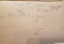
Hi Hedges, any more thoughts on my layout? Is there another way to set it up so I don't have to run 300 feet of cable?

Thanks,
Tom
 
Great info, thanks. Good point about needing to keep power the SI. I would have missed that important detail.

I don't use all 400 amps. The 400A service is spliced at the house and 200 amps goes inside the house to the main panel and 200 amps goes to a barn downstream of the house, The house 200A main panel is maxed out...no empty slots. We are in the country so no gas, everything is electric. I also have an electric car so I would probably exceed the 200 amps if everything were on at once. But I can't see ever needing 400 amps.

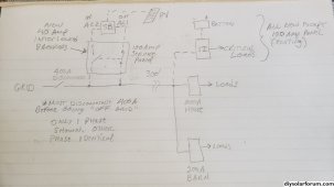
Yes, I think your idea of setting up interlocked breakers where I show the disconnect might work. There is already a 100 amp service panel there which supplies a shed, some outside lighting and two future guest cabins I plan to build. But one of the concerns is that I might be overloading that 100 amp panel so I would have to upgrade it. Beyond that though, I'm not sure I understand how this setup would be connected. This is what I think you are saying:

Solar connection with SI and SB.jpg

I don't follow how the SI would ever be able to charge the batteries or even feed into the grid with the way I have those interlocked breakers wired. What am I missing? Also when go off grid, I suppose I would also have to switch off the 400A disconnect.

Even if all this works out, 56 amps wouldn't be enough. 112 amps might. Also, I'm not crazy about the idea of having two sub panels. I do realize of course that I will need to do some rewiring to set up a critical loads panel*. I'm beginning to realize that maybe it is too much trouble to try to make this work. I came up with an alternate plan, but it is less desirable because it has more shading from trees. However I could then run a DC line from the PV to the house (or barn) and avoid all these workarounds. It will require more solar panels due to the shade, longer wire runs from the PV, and more site prep work as well. If I ran the DC straight to the house though, I could get a (hybrid?) inverter that is grid tied and can also handle battery backup. Plus it would be right next to the main panel, simplifying the integration. I know you haven't seen my property, but what would you do?

*Separate question regarding adding a critical loads panel: Why not just manually disconnect the loads (via the main service panel individual breakers) that you don't want to power during an outage?
 
You can manually disconnect loads, but with automatic load-shed, you can power A/C or whatever when there is surplus, automatically shut it off as SoC drops, resume when there is again surplus.

SolArk has 200A feed-through and also acts as a UPS, but may have some issues with AC coupling. They recommend DC coupled PV >= AC coupled, and connecting AC coupled GT PV to a separate circuit from loads (behind "generator" relay). People here say the issue is HF inverters having to reverse direction.

Sunny Island (or any similar) can charge its battery from AC on its input, even if nothing on its output. Once you transfer loads and GT PV from grid to Sunny Island's output, it can charge from them.


In your drawing, change 400A disconnect to transfer switch, one input is grid and one input is AC2 output.
Connect AC2 input to grid side of transfer switch. Max fuse/breaker 70A.

If you parallel multiple inverters, I've found QO breakers cause current imbalance. Schneider Multi-9 is better, Magnetic-hydraulic breakers like Midnight/CBI or probably Carling are better still.
 
Thanks once again, Hedges, but I'm not quite there yet. First, I think I had SI and SB reversed. I corrected my sketch so now SI connects to the batteries and SB to the array.

Also, you said "change 400A disconnect to transfer switch, one input is grid and one input is AC2 output". I think you meant one input is grid and one input is AC1 output, is that correct? Here is my updated sketch:

Revised solar config.jpg

I'm trying to avoid having to buy an expensive 400A transfer switch so the way I have it configured, I'd have to disconnect the 400A disconnect manually before switching the breaker to connect the Sunny Boy output AC1. My only question is whether I could be inadvertently backfeeding the grid during a power failure through AC2 before I have a chance to manually turn off the 400A disconnect.

Interesting that the QO breakers would cause a current imbalance. Fortunately, I don't think I need to parallel the inverters. I need about 12kw so two 6 or 7 kw inverters, one on each phase should do it.
 
You have critical loads on SI, which is correct.
You show AC2 input and AC1 output as part of SB, incorrect. Those are on SI.
You have SB upstream, SI downstream. That won't let PV charge batteries when grid is down. It will give GT PV, and battery backup. Put them back in previous order.
SI AC2 input should be fed from grid side of 400A switch, if you want SI to be able to provide UPS type backup (within its current limits) when grid goes up and down.

If UPS not desired, OK to feed from load side of 400A switch as you show in earlier drawing (SI switched) and later drawing (SB incorrect location but switched like SI could be.) No great harm if those aren't interlocked; it will just confuse SI. I did that with two separate breakers before changing wiring.

There is a block diagram at bottom of this data sheet:


If you have manual switches, 400A disconnect from grid and one other for SI AC1 output feeding same wire, NOT interlocked, then you have risk of closing both at the same time. It will blow up SI when grid is up. It may electrocute lineman when grid is down.

Simplest is a 400A transfer switch, select either grid or SI AC1 output to power your property.
If you could somehow interlock the existing 400A disconnect switch ... linkage between handles of two switches? (similar concept to the way breakers are interlocked.)
For my safety switches, I was able to get handle position microswitch. Maybe that could enable a relay connecting SI AC1 output, but it wouldn't be a positive mechanical interlock. Also, want 5 second delay after removing AC from input of SB (or input of SI) before reconnecting to other source (ensure inverter isolates or turns off; prevent backfeeding out of phase)
For swapping connections (PV DC wires), I plan to have connections inside my DC disconnect switch. Have to turn it off to open box (but can reclose after swapping; maybe you can interlock somehow.)
 
Sorry this is taking so long! I finally realize I can't do what I was hoping to do, which is to utilize the 300 feet of 4/0 wire that starts at the 400A disconnect, goes under the creek and to the house main panel. I wanted the PV to be at the same location as the 400 A disconnect because that is where the best sun exposure is. However, that would place the SB upstream of the SI which is a no go because of the reasons you mentioned (backfeeding the grid during an outage and not able to charge batteries when the grid is down). So I guess I am back to my alternate plan mentioned earlier. Thanks for helping me avoid a train wreck!

Regarding the block diagram at the bottom of that data sheet, where would the critical loads be attached?

Also, it looks like the current for the entire house goes through the Sunny Island. But they are only rated at 48 amps, so how does that work with most homes having 200 amp service? Is that why they need to be in parallel?
 
That is why I installed 4x SI, series and parallel.

European Sunny Island, and US Sunny Boy Storage, they support external 200A relay.

Critical Loads and Sunny Boys would connect directly to Sunny Island AC1 output (using a critical loads breaker panel).
Other battery backed loads are on a separate breaker panel fed through a load-shed relay. Each SI has two signal relays, and there are two SoC levels that can be set to feed them.

Given one heavy wire already run, best I can suggest is an interlocked switch letting either grid or SI feed that wire. You might mount a switch for SI AC1 output next to the 400A switch and fabricate an interlock between the handles.
When grid fails, everything shuts off. You manually throw the switches and SI powers everything, so turn off what it can't. (or run a wire to control relays disconnecting them.)

This I think puts SI and SB and PV at the 400A switch.

If you want critical loads downstream backed up without manual intervention, put them on a UPS, which could be another instance of Sunny Island.

Each SI can pass through 6.7kW to grid, or can support 12kW of GT PV if never backfeeding.
Given manual switching, you could have GT PV direct to grid when 400A switch closed, on SI when 400A switch opened, so the higher wattage supported.
 
It's starting to make sense. I see why you have four SI. I also understand about the critical and separate breaker panel loads with a relay that is controlled by SI based on SOC. Very handy.

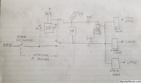
Thanks for the suggestion on how to possibly incorporate the 4/0 wire. Yes, putting the SB, SI and PV at the 400A disconnect location would work. Here is what I think it would look like:

Solar all at 400A disconnect.jpg

Is this what you had in mind? I am assuming the SI cannot backfeed the grid through AC2.

The drawbacks to this setup are that the batteries will now be outside (or in an unheated enclosure). Also, its not necessary, but if I want automatic load shedding, I'd need to run a signal wire to the house.

I don't mind manual intervention so don't really need another SI.
 
SI is configurable to backfeed grid through AC2 or not. Including dynamic switching if either generator or grid could be connected.

Here's 4 older model 5048US for $4800. Says pick-up only. Maybe for all 4 he could strap them on a pallet and have a trucker load it with pallet jack.


Here's 2 newer model 6048US, probably unused. In weather proof box, not as good ventilation as manual says (maybe add awning and leave doors open. Or duct air inlet or outlet directly out of box.)


The way you've drawn it, transfer switch would have to carry the 400A (and no interlock to existing 400A switch necessary.)
You could do something different such as transfer switch 60A either AC2 or AC1. Then you do need interlock to 400A.
 
I would want SI to backfeed the grid when the grid is up, but not when the grid is down. Is that also configurable?

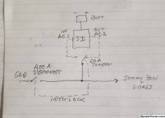
OK, think I got it. Like this?

Solar all at 400A disconnect, 60 A transfer sw.jpg

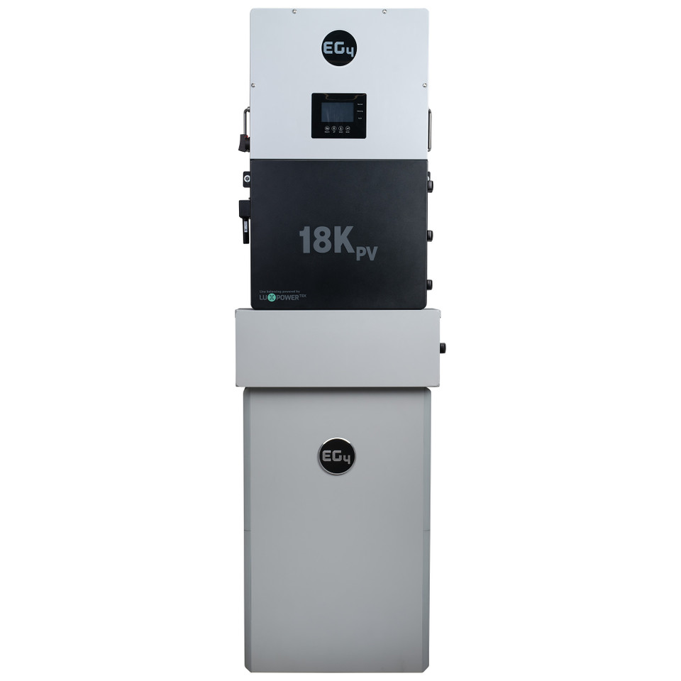
Something occurred to me. If I have the SI and SB right next to each other, then I don't have to worry about AC coupling or even separate inverters for that matter. Instead I could just get an all in one inverter and maybe not have to deal with the transfer switch. I think that would also be cheaper. Something like this: EG4 Inverter
 
Yes, wired like that.

In your circuit, SB would backfeed grid when connected, charge SI batteries when offgrid. SI would keep batteries charged by grid.
SI only backfeeds grid if there is DC coupled source charging battery higher than its setpoint. It does not have firmware to charge batteries during low rates and backfeed during high rates.

Complete EG4 ESS:


Also consider SolArk. People report good results and responsive support.

Some of these support 200A pass-through, good if you don't need full 400A.
They would also support time shifting, charging battery (maybe only from PV to comply with utility rules) off peak, discharge battery to backfeed grid on-peak.
 
Yay, I finally got it! Thank you so much for taking the time to help me out!!! Now I have to decide between the SI/SB combo and the Solark or EG4/Luxpower all-in-one type inverters. I like the simplicity of all in one, especially with 200 amp pass through, as well as the cost savings. Thanks also for the link to the complete ESS, I wasn't aware they were available, but it makes installation so much easier.

I guess I have a lot to consider now so hopefully I won't be bugging you any more....uh, well at least until my next question.

Thanks so much,
Tom
 
Back
Top