diy solar

diy solar

Adding EMT / Conduit to an existing panel and trough install sol ark

byteharmony

Sunny side up please.
Joined
Jul 29, 2022
Messages
233
Location
Milwaukee
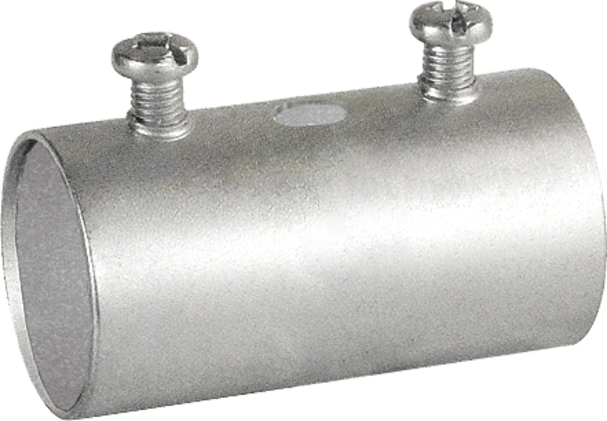
How do people add additional EMT paths from a panel to a trough after the install and mounting are all finished? Is it as simple as cutting the EMT short and leaving the top and bottom of the set screw connector void of EMT? Put the EMT in the connectors all the way first then expand those connectors one at a time using the set screw to hold the EMT floating between the two connectors?

Take these photos of systems as good examples.


As long as that floating EMT pinned by set screw approach works then what do people with installs like this do?

How is this done? blind LB, wiring behind the wall, conduit to conduit pull elbow?
Unless there is access from behind my understanding is you'll need to pull apart the wall to get more conduit in there.
 
I think most people put the conduit in while the install is in process. With two fixed components, the options are to move or bend something or have one of the connections perpendicular to the other.

If you think you might need to run more wires in the future, you should put in bigger/more conduit with the initial install.

Can you share pictures of what you're trying to do? An actual problem is easy to provide useful help with that a theoretical problem.
 
Is it's an indoor installation then you can use rigid with threaded ends and use locknuts directly on the conduit
 
Can you share pictures of what you're trying to do? An actual problem is easy to provide useful help with that a theoretical problem.
I don't have the problem yet. I'm going to install a 2" to run power from Sol Ark to the panel.

The actual problem is a year or two from now when I want to run 2 or 3 sub panels and I have to add more conduit between the trough and the panel.

Is it's an indoor installation then you can use rigid with threaded ends and use locknuts directly on the conduit

Indoor
 
You could use PVC with a female adapter on each end and chase nipples screwed into them from the insides of each box. If you like metal, then the same could be done with a rigid nipple and rigid couplings.
 
You could use PVC with a female adapter on each end and chase nipples screwed into them from the insides of each box. If you like metal, then the same could be done with a rigid nipple and rigid couplings.
Would this require rigid pipe or could you use these kinds of fittings with EMT?

These are great ideas!
 
Would this require rigid pipe or could you use these kinds of fittings with EMT?

These are great ideas!
You could use EMT if you have the space. Two EMT connectors with a rigid coupling on each end will work if you can fit it in.
 
You could use PVC with a female adapter on each end and chase nipples screwed into them from the insides of each box. If you like metal, then the same could be done with a rigid nipple and rigid couplings.
If using a rigid nipple then you don't need the couplings in an indoor installation, just use 4 locknuts (one on each side of the boxes).
 
If using a rigid nipple then you don't need the couplings in an indoor installation, just use 4 locknuts (one on each side of the boxes).
The problem is that the inverters and trough are already in place. So my idea is a solution that doesn't require too much disassembly.
 
The problem is that the inverters and trough are already in place. So my idea is a solution that doesn't require too much disassembly.
Using a rigid nipple and locknuts requires no disassembly in most cases since the nipple is skinny enough to fit through the knockouts
 
The problem is that the inverters and trough are already in place. So my idea is a solution that doesn't require too much disassembly.
You just need to use a slip coupling in the middle. Cut the conduit to length, then cut in half. Put the two pieces into the end fittings, put on the slip coupling on one side, align the conduits and then tighten things up.

 
Last edited:
You just need to use a slip coupling in the middle. Cut the conduit to length, then cut in half. Put the two pieces into the end fittings, put on the slip coupling on one side, align the conduits and then tighten things up.

Yeah but those aren't readily available solutions. You can get them, but they're probably special order from the supplier.
 
But how do you get lock nuts on both sides?
Ah you're right. I just remembered that the one time I had to do that I only ended up using locknuts on 1 side. You could do two on one side and one on the other without disassembly.
 
Cut the EMT just short enough to get it in place. Then cheat it equally between the connectors. As long as the set scew engages on both ends, you are fine.
Usually the length of one connectors threads is enough.
 
But how do you get lock nuts on both sides?
If you go that route you just back off the locknuts on the outside portion to the ends of the threads which gives you a few inches of play to insert in one box and then slip into the second before locking everything in place.
 
You could use EMT if you have the space. Two EMT connectors with a rigid coupling on each end will work if you can fit it in.
Yep, now this makes sense to me. The rigid Coupling makes the emt female threaded to be able to screw in from the inside of a panel / trough.
But how do you get lock nuts on both sides?
Also a great idea if you're holding the rigid pipe and have a threader. Nice and clean.

You all are full of wonderful ideas. I have learned so much, thank you!


Given the cost and simplicity. I'm going to go with Tim. I'll post photos when it's done ?
Cut the EMT just short enough to get it in place. Then cheat it equally between the connectors. As long as the set scew engages on both ends, you are fine.
Usually the length of one connectors threads is enough.
 
Back
Top