diy solar

diy solar

Ampinvt split phase in an RV shore connection?

johntaves

New Member
Joined
Mar 31, 2020
Messages
221
I have an ampinvt 6kw split phase inverter in my RV. I don't need 240V. I figured it was the easiest way to power the A/C, stove, oven, disposal, and dishwasher without juggling 2 inverters.

I want to retire the 24V power supply that I use to charge the batteries, and the transfer switch. But the wiring has me scratching my head.20230827_145147.jpgThe inverter has just two hot legs as input and Ampinvt replied that I should connect just the 2 hot legs of a 240V supply, and not the ground or neutral.

However, before I got that information from them, I had connected the mains ground and white to the output ground and neutral and a single 120V hot to both HOT1 and HOT2 on the input.

It seemed to work fine. It ran current to the battery, and when I altered the voltage that triggers charging to be below the battery voltage it stopped charging and the battery was providing the normal current for the DC loads. The microwave and oven clocks were on, but that was the only AC load.

I am wondering how this inverter/charger works?

I assumed that these all had transfer switches, but maybe it does not. But if not, does it take in the 240V and produce the split phase output? If so, how does it deal with the fact that there was 0V across the input?

If it does have a transfer switch, then how would it produce the 2x 120V legs a 240V input?
 
I can use a 50A campsite connection, the neutral from the 50A will not be connected to anything. But Ampinvt is saying that the ground should also not be connected. Does this make sense? If either of the hot legs shorted to the chassis it would be rather nasty without a path back to the input to trip the breaker.
 
Well I guess nobody else is going to try this.
My concern is the lack of some important electrical basics which could lead to some potentially lethal safety concerns. And I’m not being dramatic- this is critical stuff to get done correctly.
I’m not an electrician fwiw.
If so, how does it deal with the fact that there was 0V across the input?
Did you test for voltage across the input? Because-
I had connected the mains ground and white to the output ground and neutral and a single 120V hot to both HOT1 and HOT2 on the input….it seemed to work fine
AC input Hot1 and AC Input Hot2 are each 120V with 240V across them. It is not zero volts.

An example is my 240V TiG welder which uses a 6-50P. Two hots and a ground, the two hots having their phased waveforms combined for 240V.

I don’t know your inverter whatsoever but it appears to use the same principle.

have an ampinvt 6kw split phase inverter in my RV
I’m assuming this is an AIO (All In One) of some sort.
It ran current to the battery, and when I altered the voltage that triggers charging to be below the battery voltage it stopped charging and the battery was providing the normal current for the DC loads
Ampinvt replied that I should connect just the 2 hot legs of a 240V supply, and not the ground or neutral
I had connected the mains ground and white to the output ground and neutral and a single 120V hot to both HOT1 and HOT2 on the input.
Did your unit not come with a manual containing wiring instructions? What did it say? Because…
assumed that these all had transfer switches, but maybe it does not
…you have to assure their wiring instructions and intentions are followed for the transfer switch to handle N-G bond properly, or assure that it IS grounded properly so the G/green/bare does not carry current.
 
Ampinvt is saying that the ground should also not be connected
It might make sense if they are describing only the input terminals but I think that either the wiring diagram / instructions in the manual should be followed or they need to provide one that depicts grounding if the manual is not adequately written.
 
AC input Hot1 and AC Input Hot2 are each 120V with 240V across them. It is not zero volts.
I am describing the typical situation where an RV owner will use a 15 or 30amp connector that delivers the same single 120VAC hot to both HOT of the nema 14-50 plug. So both legs of HOT have the same phase, and therefore have 0V between them. RVs do not have 240VAC loads, so this is totally fine and useful. The 50amp plugs are used to deliver more amps, the 240VAC is generally ignored. Of course some RVers will have a welder on board and when they use the 15 or 30 mains, that welder don't weld.
 
Their wiring diagram is "high level". It does not provide detail, or to put it bluntly, it is crap.

I am in the middle of an enormous back and forth via email with ampinvt. It seems like the email person is translating my words to the electrical engineer and the electrical engineer then answers the wrong question, or the emailer replies back with a BS answer. For many rounds they were trying to convince me that the ground from the mains cannot be connected to the chassis with battery negative also connected. I finally got them to recant that stupid statement, by telling them that every car, RV, truck has battery neutral connected to the chassis and that no sane installer will leave the mains ground dangling.


For example my questions are in bold, and their answer is not bold:
"Does the inverter built-in conversion switch bond ground to neutral when the inverter is supplying the 240/120VAC output, and does it disconnect that bond when it is passing the mains through to the output?” Yes, the inverter automatically recognizes the built-in automatic protection.
"Is it OK to connect input neutral to output neutral"NO,The two midlines cannot be confused.
" and is it OK to deliver the same phase 120VAC to both HOT1/2?"Yes

Notice the first question is not answered. They would make a great politician, but this is garbage for getting facts.

And notice that these answers are inconsistent.
If it is OK to deliver the same phase 120VAC (note that it will be 0V between HOT1 and HOT2) then the neutral from the mains must be connected to something. If mains neutral is not connected, then the current is being delivered back to the mains via ground, or they do not bond ground and neutral, and thus mains current does not go anywhere.
-------------------------------
I am trying to get them to clarify the neutral to ground bond, and the nature of their "transfer switch".

I suspect that they do not have a mechanical transfer switch in the unit that connects/disconnects the inverter and mains to the output. I say this because they have only one neutral connection as shown in the photo above.

If this is correct, then they are unable to properly bond neutral to ground when inverter is used, and disconnect that bond when the mains are passed through. If it is never bonded, then in the event of a short to the chassis, the metal in the RV will be energized with no path back to neutral to trip a breaker. A human will complete the circuit and get a shock. I could make this bond myself, but then when the mains are passed through, there would be 2 bonds. One supplied by the mains, and one in the RV, which could lead to annoying ground fault interrupts.
-------------------------------
What I am asking this forum is for speculation on how it is built. I do know that it has a nice big round transformer. Its low price and this big doughnut is a big selling point for me. It should be more efficient than the big square transformers found in the SUNGOLDPOWER/AIMS long rectangular alternatives.
  1. maybe they rectify the 240VAC input and send that into the inverter, so therefore the inverter is always supplying the output power, and I can bond the ground and neutral outside the inverter. But that makes no sense to me because they would need 2 transformers, right?
  2. maybe they have a transfer switch that sends mains to the output, but they are only switching the 2 hot inputs. Is that possible? How does a different load on each leg work? Maybe the transformer handles that by effectively routing the excess on one leg to the other leg. Does that explain why they say that you cannot connect the mains neutral to the output neutral?
I am concluding that it must be #2. So what happens when you do connect the input neutral to the output neutral? Does it fry the inverter if there is too much load on one leg? Each leg on my panel has a 30amp breaker, which is 3600W, which is more than half of the inverter's rated capacity of 6000W, although it can surge to 3x that.

EDIT: The transformer must be capable of shifting the different loads on each leg. However, if the mains neutral is connected to the output neutral, then we cannot predict the following. The transformer could balance the load and therefore no current flows on the neutral back to the mains. OR, the mains neutral will take the differential load back on its neutral. But that means that it is also possible that the two could go nuts and overload both neutrals, right? I don't buy this thinking.

EDIT: Maybe they have transistors/mosfets to connect/disconnect the mains to the output and to the transformer and these can have a bogus potential caused by the 2 different neutrals being connected?

And if I only connect 120VAC to one or both inputs, with, of course input neutral connected to the output neutral, then why is there a problem?

I could provide my own relay switch to connect ground/neutral when mains are in/out.
 
Last edited:
am describing the typical situation where an RV owner will use a 15 or 30amp connector that delivers the same single 120VAC hot to both HOT of the nema 14-50 plug
Through an adapter.

I was describing the terminals of your inverter.
But good luck with your project.
 
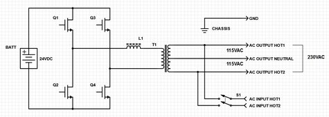
i believe your ampinvt inverter is wired like this:

inverter_diagram.jpg

In inverter mode, S1 is open, the inverter creates 120/240VAC from the battery using spwm on the mosfets. In bypass mode, S1 is closed, AC input is connected to AC output, and the transformer creates the neutral with its split output winding. In bypass mode, the battery is charged using the mosfets as a boost converter.

The reason they tell you do not connect input neutral to output neutral is that with both transformer legs and neutral connected to grid, the transformer will attempt to balance the grids 120VAC legs, causing circulating currents, and may overheat the transformer. no problem if you just use a single 120VAC leg.

for operation without split phase grid power, you could connect a single leg of 120VAC across output neutral and HOT1 input, leave HOT2 input unused. The transformer will create the second leg of 120VAC on the output, and should still be able charge the battery. which is basically what you did when you first connected it, but when you connected both input legs to the same 120VAC grid leg, im not sure how that worked. i would think the transformer would cancel them out, because the windings are opposite polarity, and not be able to charge battery. that is why i would just connect grid to one of the HOT inputs, leave other input unconnected.

the GND just connects to the chassis so you dont get shocked touching it, this ground could be battery negative, vehicle chassis, grid ground, neutral output, whatever

I have the 5000W 48V version, but i may have a newer model or something, it is wired just like that, the rear panel input has 120VAC input HOT1 and NEUTAL instead of HOT1 and HOT2. input neutral is same as output neutral and neutral on the receptacles.

however, use my advice at your own risk, i am not responsible for smokey results :giggle:
 

Attachments

  • inverter_diagram.jpg
    inverter_diagram.jpg
    181.6 KB · Views: 1
Last edited:
which is basically what you did when you first connected it, but when you connected both input legs to the same 120VAC grid leg, im not sure how that worked. i would think the transformer would cancel them out, because the windings are opposite polarity, and not be able to charge battery. that is why i would just connect grid to one of the HOT inputs, leave other input unconnected.
I think I agree with this. I was not properly realizing that the transformer can create the other leg of output. I was thinking it had a full transfer switch that would disconnect the output from the transformer and send the input straight out. I think your diagram makes more sense.

I will reread the emails from Ampinvt and see if I can unambiguously conclude they are telling me to wire it this way.

jt
 
Back
Top