diy solar

diy solar

Automatic toggling of power source (Vehicle vs. House battery)

daisyChain

New Member
Joined
Nov 25, 2023
Messages
10
Location
WI
I want a way to automatically switch the power source of my sound system (amplifier) between the vehicle battery and the house battery. When the vehicle (alternator) is running, I want to use the vehicle battery(alternator) as the source of power. When the vehicle is not running, I want to use my house battery as the source of power.

More details: I don't mind if the sound system needs to shut off for some duration of time during this automatic switching mechanism. The main reason I am going through the trouble of the 'complicated' relay switching logic is to make sure that the high (unsteady) voltage from the alternator does not get connected to the output from the DC/DC converter because there are many other devices using the steady (precise) 12v output from the DC converter and I want to make sure these devices don't receive the alternator's unsteady 14+ V.

I believe I have captured all cases that I need to consider as far as the microcontroller's sensors are concerned (including taking into account precautions for failed relays whose outputs are stuck connected). If the microcontroller turns ON at any point in time, it will correctly detect the current state and correctly set triggers as necessary. Similarly, if the microcontroller turns OFF at any point in time, the result (assuming the relays don't fail) will be that the amplifier loses power and the sound system stops outputting sound (which I am ok with) (if a relay's output was connected at the point in which the microcontroller turned OFF AND the relay failed - causing its output to stay stuck connected, then the amplifier would still be powered and outputting sound).

I have the ability to program a microcontroller with this logic, but I am fairly new to electrical systems and relays, so I want to make sure this is a sound (and safe) approach and perhaps if I am missing something (let me know), or if there is an alternative/easier way to achieve what I am trying to do?
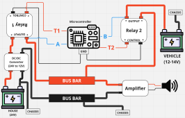
1702668156464.png
The logic I will employ is as follows:

- IF A senses 12V AND B senses high voltage (~14 V) it will indicate that the vehicle (alternator) is running, relay 2 is disconnected, relay 1 is connected, and the amplifier is using the house battery.
+ THEN the microcontroller will then disengage relay 1 (via T1).

- IF A senses ground (0 V) AND B senses high voltage (~14 V) it will indicate that both relays outputs are disconnected, the vehicle (alternator) is running, and the amplifier is NOT powered.
+ THEN The microcontroller will then engage Relay 2 (via T2).

- IF A senses (Non high) voltage (~12 V) AND B senses (Non high) voltage (~12 V) it will indicate that the vehicle (alternator) is NOT running and the amplifier is powered by EITHER the vehicle battery OR house battery.
+ THEN The microcontroller will then disengage relay 2 (via T2).

- IF A senses ground (0 V) AND B senses (Non high) voltage (~12 V) it will indicate that the vehicle (alternator) is NOT running, both relays outputs are disconnected, and the amplifier is NOT powered.
+THE The microcontroller will then engage Relay 1 (via T1).

In short hand pseudo code the gist of this is:
Code:
if A == 12 and B >= 14:
    T1.set(OFF)
if A == 0 and B >= 14:
    T2.set(ON)
if A == 12 and B == 12:
    T2.set(OFF)
if A == 0 and B == 12:
    T1.set(ON)
 
Why not just plug a dc/dc controller from the chassis to the house? This will charge the house battery when running and not when off, giving you the same effect.

If you're worried about voltage stability then a dc/dc converter will fix this. You can run a 12/12 converter and it'll convert 10-18v to the exact voltage you dial in.
 
Why not a simple dual position relay, with the NC terminal connected to the battery and the NO terminal connected to vehicle power, and the common to the amplifier, then connect the relay coil to an ignition-on source? That way, when the vehicle is ignition off, you're running on house battery, and it simply clicks the relay to vehicle power for the amplifier when you start the engine.
 
Why not just plug a dc/dc controller from the chassis to the house? This will charge the house battery when running and not when off, giving you the same effect.

If you're worried about voltage stability then a dc/dc converter will fix this. You can run a 12/12 converter and it'll convert 10-18v to the exact voltage you dial in.
Apologies, I only diagrammed part of my system above. I do have a separate DC/DC isolated converter hooked up to charge the house battery from the alternator. Since it is isolated, it doesn't flow the opposite way (from the house battery to the vehicle battery) (which is what I desire since I don't want to drain the vehicle battery when the vehicle is off).

I don't quite follow your other suggestion of adding another (3rd) DC/DC converter to the system. I am not sure how that would solve my automatic power source switching problem or where you intend it to sit in the system? Where would this be getting power input from and where would this be delivering output to? Could you elaborate? Thanks.
 
Why not a simple dual position relay, with the NC terminal connected to the battery and the NO terminal connected to vehicle power, and the common to the amplifier, then connect the relay coil to an ignition-on source? That way, when the vehicle is ignition off, you're running on house battery, and it simply clicks the relay to vehicle power for the amplifier when you start the engine.
Ahha, this sounds exactly like what I want and it implements the logic that I want. Is there a proper name (or another name) for this type of relay. I had originally searched for something like this but couldn't find one that implemented the logic I was after, but if one exists, then by all means it will simplify my setup to do exactly what I want. When I search for "dual position relay" I am not coming up with items that have this defined as their name (nor the desired functionality). FWIW, I am needing it to handle 40 amps. Thanks.
 
Apologies, I only diagrammed part of my system above. I do have a separate DC/DC isolated converter hooked up to charge the house battery from the alternator. Since it is isolated, it doesn't flow the opposite way (from the house battery to the vehicle battery) (which is what I desire since I don't want to drain the vehicle battery when the vehicle is off).

I don't quite follow your other suggestion of adding another (3rd) DC/DC converter to the system. I am not sure how that would solve my automatic power source switching problem or where you intend it to sit in the system? Where would this be getting power input from and where would this be delivering output to? Could you elaborate? Thanks.
You just need to add DC-DC 12/24 from chassis to house with the switch plugged into your ignition so it only turns on when engine is running. The stereo and everything will all be connected to your house then when the engine is on the dc-dc converter is charging the house batteries, or if they're over like 80% it'll use the engine to run all loads. When you turn the key off the 12/24 dc-dc converter turns off and you use your house batteries.

Because you have a 24/12 converter all the power will be a constant voltage
Ahha, I understand now what you are saying. Thanks for the clarification.

I am OK with the 14V (fluctuation) going directly to the amplifier, but I just don't want it to go to the 12V items that the house battery is supplying power for since some of them are more specific about the exact required voltage.

Your idea would indeed achieve the 'automatic' switching mechanism that I desire. However, I was avoiding this approach for 2 main reasons: (1) it results in a loss of power (due to inefficiencies in conversions) and (2) it depends on both of my converters (12v->24v) and (24v->12v) in order to run the amplifier.

(1) means that when the vehicle is on there is ~14V (which is suitable for the amplifier) that goes through a conversion to 24V (loss in efficiency due to conversion) and then goes through another conversion back down to 12V (another loss in efficiency due to conversion) and then to the amplifier, so my thought was to avoid this double inefficiency loss if possible.

(2) means that if either of those devices weren't working then the amplifier is out of commission, even though the power supply from the alternator is ready/willing to supply the amplifier with power. (I understand the same can be said about my microcontroller and relays - if they are not working then my amplifier is also not working, however I see the difference in that I would like to have the ability to allow the amplifier to be powered independently of the house electrical system - whereas I am considering the dc/dc converters part of my house electrical system).
 
Plain old 5 pin Bosch styke automotive relay would do it. Cheap and easy.
Thanks. I watched this video and I believe I understand how it works and that it does indeed do what you described and what I desire. I think this is indeed the right direction to go, and will simplify my set up. Thanks for pointing me to this device.

My only concern/question is what the fail state of these type of 5 pin relays looks like. Do they stay stuck in the same state they they were in when the failure happened (which would be fine) or is it possible that they could fail and bridge both of the outputs (tunring both lights on in the example video) - essentially connecting the alternator output with the my converter (24V to 12V) output - thus sending 14V to my appliances that require the stable fixed 12V. I will have to research this a bit more. Perhaps their failure rate is low and the bridging is not a possibility, in which case this will work out just fine.

Thanks for your knowledge and help!
They fail in only one position. It physically can't make contact to both at the same time (it is a physical lever arm inside the relay, essentially). Most likely if it failed it would be in the NC position, which would mean in this case house battery.
 
Seems really complex to use a micro-controller for all that stuff. A simple DPDT transfer switch/relay, common to load, inputs to House / Auto batteries. Control to the auto/ignition accessory power relay/bus, but I'm struggling with the "unsteady" alternator note since you want to connect to it when it's running. If that's an issue you need a DC-DC power supply in front all the time.
 
You need a high current 5 pin change over relay, 12v coil. Activate by ignition on, or D+ alternator charging, or a manual switch.
Having series fuses would protect against faults and over current issues.
Thank you! I've got the fuses for the system as well, just didn't want to clutter up the diagram for this particular task I was trying to figure out. Thanks for the link and information.
 
They fail in only one position. It physically can't make contact to both at the same time (it is a physical lever arm inside the relay, essentially). Most likely if it failed it would be in the NC position, which would mean in this case house battery.
Great, looks like this will work great instead of my complicated approach, thanks again.
 
Seems really complex to use a micro-controller for all that stuff. A simple DPDT transfer switch/relay, common to load, inputs to House / Auto batteries. Control to the auto/ignition accessory power relay/bus, but I'm struggling with the "unsteady" alternator note since you want to connect to it when it's running. If that's an issue you need a DC-DC power supply in front all the time.
Yes, I understand now. This specific relay does exactly what I was after. I'm fine with the amplifier receiving unsteady voltage, its just some of the other items connected to the 12V source from the house battery that I don't want exposed to the unsteady voltage from the alternator.
 
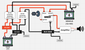
Here's how the system will look with the 5 pin relay. Thanks again everyone for your help.

1702686761119.png
I added the isolated DC/DC converter to this diagram as well (although it wasn't apart of my original posted diagram and it doesn't affect the automatic toggling of the power source).
 
Here's how the system will look with the 5 pin relay. Thanks again everyone for your help.

View attachment 183235
I added the isolated DC/DC converter to this diagram as well (although it wasn't apart of my original posted diagram and it doesn't affect the automatic toggling of the power source).

Depending on how fast the relay can switch, you might want to put an audio amp power capacitor on the amp-side of the relay. Amps will spark too if the voltage drops down too low during switchover.
 
Depending on how fast the relay can switch, you might want to put an audio amp power capacitor on the amp-side of the relay. Amps will spark too if the voltage drops down too low during switchover.
Putting a capacitor on that side of the relay will increase the current spikes through the relay when it switches the amp from one voltage level (house) to another (vehicle battery)

To the OP:
The relay is the implementation for your goal, but what's the point of switching power sources?

Once the engine is running, the alternator is charging the house battery which is powering through amp. Sure, you've got some losses powering it through 2 DCDCs, but swapping input power while the amp is operating, doesn't seem like it would be healthy for the internals of the amp. In my opinion, I'd take the hit in efficiency vs the possible equipment damage.
 
I did this on my first build, a custom class-c type.
side note: I ran my driver power seat off the house battery all the time. When running the alternator feeds both house and starting battery anyway, so no reason to care which it runs off of while driving and the house battery was very close to the drivers seat making wiring the new power seat easy.

For sound system, that includes 300 watt sub, I wired the 12v ignition feed to an A-B toggle switch so I could use radio normally when driving and it goes off when engine off, or switch it to house battery and radio is on when toggle is on B (house). The constant 12v memory power stayed from starting battery as no need to switch it, or was that constant also what powered the radio?? I cant remember, sorry.
Originally the radio main 12v was from the ignition power or at least from the fuse box, but doesnt really matter here.
You just need to add in the 24v to 12v converter from your house battery before the toggle switch, which I assume u have already in an rv setup.

I would run audio off the house battery and toggle the ignition wire between the vehicle ignition and (when camping and parked) toggle it over to get 12v from the house battery converter. SImple.

Electrically is the same no matter which battery is switched while driving, meaning it did not drain the house battery when switched to house while driving bc the alternator was actually what was powering it.

Your systems seems very complicated.
 
Last edited:
Putting a capacitor on that side of the relay will increase the current spikes through the relay when it switches the amp from one voltage level (house) to another (vehicle battery)

To the OP:
The relay is the implementation for your goal, but what's the point of switching power sources?

Once the engine is running, the alternator is charging the house battery which is powering through amp. Sure, you've got some losses powering it through 2 DCDCs, but swapping input power while the amp is operating, doesn't seem like it would be healthy for the internals of the amp. In my opinion, I'd take the hit in efficiency vs the possible equipment damage.
If I understand correctly, the purpose (or benefit) of adding a capacitor would be to have a "seamless" transition when I switch power sources (vehicle/battery). This would mean that if there was music playing through the amp, then it would continuously play whenever the power source would switch (vehicle/battery). Is that correct? If this is the correct understanding about the capacitor, then I don't think I need it because I don't care whether or not the music has a "seamless" transition when I switch power sources. It is OK if it stops playing for some amount of time when the switchover takes place and then begins playing again after some amount of time.

The point of switching power sources for me is several fold. A little of the rationale is in this post: https://diysolarforum.com/threads/a...ce-vehicle-vs-house-battery.74877/post-949733 . The gist of it is that I want to NOT have it hooked to ONLY my car battery so that I can use my amplifier when my car is off and not worry about draining my car battery. On top of that, I'd like to use the amps from my alternator when the car is running as opposed to using the amps from my house battery, since the house battery capacity is reserved for when the vehicle is off.

>> Sure, you've got some losses powering it through 2 DCDCs, but swapping input power while the amp is operating, doesn't seem like it would be >> healthy for the internals of the amp. In my opinion, I'd take the hit in efficiency vs the possible equipment damage.


Apologies, I tried to simplify my problem/question when I originally posted so that it would be easier for others to understand the main issue I was trying to solve. I will explain a bit more about the bigger issue that exists if I get rid of the relay switching idea and ONLY hook up the amplifier through the house battery system (which is being charged by the alternator when the vehicle is running, and hence still performs the "switching" power sources mechanism....

My 12v to 24V DC/DC Isolated Converter is 15 Amps. That means it produces 15 Amps @24V. If we ignore inefficiencies, this comes out to 30 Amps @12V. So this device will draw 30 amps from the alternator to charge the house battery. If I hook up my amplifier (which needs a 40 Amp fuse - but just for sake of understanding we'll assume it normally draws 20 amps) solely to the house battery (through the 24V to 12V DC/DC converter) then 20 amps @12V would be used by the amplifier, this is 10 amps @24V. These 10amps are coming from the house battery. So the alternator is supplying 15 amps (@24V) to the house battery, and the amplifier is drawing 10 amps (@24V) from the house battery. This means the effective charge from the alternator to the house battery is ONLY 5 amps (@24V). In this scenario the tax on the alternator is ONLY 30 amps (@12V) (again assuming we ignore inefficiencies, I understand that more will be drawn in order for the DC/DC converter to produce its output).

If instead, I am able to hook up the system I proposed above (using the single 5 pin relay), then I would have an effective charge rate from the alternator to the house battery of 15 amps (@24V) AND the alternator would have a 20 amp draw (@12V) from the amplifier, thus making the total tax on the alternator 30 amps (@12V) + 20 amps (@12V) = 50 amps. This way, I would use more amperage from my alternator but I wouldn't sacrifice any of my house battery charging. I believe I am far from my alternator's max potential, so I don't believe this will be putting any strain on the alternator.

Even if my guess at the amplifier's current draw is incorrect, the point is still the same (unless my understanding is incorrect somewhere, please correct me if so), thus I don't want to sacrifice my alternator to house battery charging capabilities if I can avoid it.

All of that said. If the 'power source switch over' is going to cause an issue (or potentially damage) the amplifier, then I'd rather not have that happen. So I am curious if I can still keep the gist of the automatic power source switching mechanism whilst addressing the amplifier damage issue? My amplifier has the ability to turn on via 3 different methods: (1) - Remote Wire (12V = ON, 0V = OFF), (2) DC offset on the RCA input (basically detecting whether there is an audio signal coming into the amplifier), and (3) - Full audio signal on the RCA input (more thorough check on the signal coming in, but this has a 30 second delay before turning off the amp).

I think (1) sounds promising in terms of safely turning off the amplifier before the switch over happens. I am just not sure what the right mechanisms would need to be to make this happen. As far as switching from the alternator to the house battery source, I could use the ignition wire to notify the amplifier to turn off. I would need to find a different (delayed) trigger for the relay however. I guess I could use a microcontroller in conjunction with the 5 pin relay. Instead of the ignition wire going into the relay, it would go into the microcontroller. Then the microcontroller can correctly turn on/off the amplifier when necessary and then send the trigger signal to the relay when necessary. The microcontroller is already tied to the radio system, so it can control when audio output is being sent to the amplifier.

I am thinking something along the lines of...when the ignition is sensed, block audio output from the radio, send the off signal to the remote wire of the amplifier, trigger the relay to perform the switch over (from house to vehicle), send the on signal to the remote wire of the amplifier, allow audio output from the radio. Then the opposite when the ignition is shut off... block audio output from the radio, send the off signal to the remote wire of the amplifier, trigger the relay to perform the switch over (from vehicle to house), send the on signal to the remote wire of the amplifier, allow audio output from the radio.

Maybe I am missing something or theres an easier way to achieve this so let me know if either or both are the case. Thanks for all the info so far.
 
Back
Top