• Have you tried out dark mode?! Scroll to the bottom of any page to find a sun or moon icon to turn dark mode on or off!

diy solar

diy solar

Backup down under

wattmatters

Solar Wizard
Joined
Apr 16, 2021
Messages
4,136
Location
NSW, Australia
Greetings from down under. I live in a home near the small town of Bellingen, in northern NSW, Australia. Glorious country:

IMG_1965.jpeg

That's our home at left centre, and obscured by the tree and slightly off the left of the image is a secondary dwelling where my Mum lives. 12 acres, behind our home (to the left) is bushland. Aside from that, the beach I take our dog to is 20-min away:

IMG_2557.jpeg

We've been here living the dream for a little over five years now.

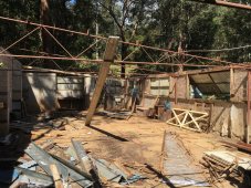
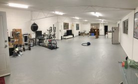
While semi-rural (~1km out of town) we have 3-phase grid connected power. What you can't see in the pic above is another building which was originally a builder's workshop, hence the 3-phase supply. That building was in ruins when we got here but I have resurrected it and created a mancave escape with 115m² of indoor mancave goodness. :)

Before:

IMG_0201.jpeg

After:

IMG_2183.jpeg

Has since been decked out with bed, furniture, storage, workbenches and is a self contained living space / office / workshop / training facility.

I had installed an 11kW grid tied solar PV array, with a Fronius Symo inverter on the primary dwelling:
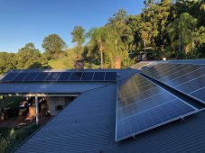
IMG_2176.jpeg

It's great, has made a massive difference to our power bills and our investment will be recovered inside of 5 years. Our home is all electric except for the hot water in the second dwelling and mancave which each have Rinnai continuous flow gas HW units with 45kg propane tanks. Heating/cooling is all via reverse cycle aircon. Apart from working on the energy supply side with the solar PV, we've also made a few changes on the energy demand side and have managed to reduce our average electrical energy consumption over the past 5 years by 19kWh/day.

That's the good stuff. The downside is rural electrical supply is less reliable than what I was used to when we lived in inner Sydney. With the Fronius meter data I collect, I have been able to keep a complete record of our grid outages and each year we average a dozen longer outages totalling about 36 hours. Plus a lot of shorter brown-out type outages. It's seasonal, with Summer storms being responsible for half the outages.

The longest was a 2-3 days outage after a mini cyclone took out power lines across the district, and it was when we had family staying for holidays with fridges full of all our Christmas food and goodies. Not happy Jan.

It was clear based on our experience over several years that grid outages were going to be an ongoing fact of life here so I did what most probably do and started with a small cheapie generator and lots of extension cords. That was OK and got us through a few outages but it was tedious to set up and put away again, only to have another outage soon after. And once we decided to build the extra dwelling for my elderly Mum to live in, well we were going to need a better solution for some energy security.

So about 18 months ago I decided it was time to have backup power supply wired into the main circuit board. Keeping it simple I started with a 15A power inlet (we are 230V AC here, so that’s enough to handle 3.5kW) which can supply all the home’s circuits via a cutover switch.
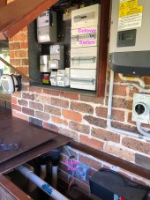
rEWRhw3.jpeg

While the home is supplied via 3-phase, when on back up supply the home is effectively on a single phase supply. We have no 3-phase appliances or loads, and if we did they would not be connected to the backup side of the cutover switch in any case. I kept the oven and induction stove on the grid-only side - and the oven clock tells us when the grid power comes back on, it also makes a bleeping sound on power up so we know when we can cut back over to grid power.

I bought a pre-loved Yamaha EF3000iSE inverter generator with keyed electric start in near new condition for half the new price. It’ll supply up to 2.8kW continuous without problem. It’s quiet and easy to start/use and this has been our mainstay for power backup and we’ve been very glad to have it.

However, despite how easy it is to use, the wife is still not keen all that keen on using the generator when I’m not home, plus if we were both not home my Mum would have little hope of turning it on.

Hence I wanted to move up another step with our backup power system to make it even easier to use and also provide automation for my Mum for the occasions when we are both away.

So I’ve started an off-grid inverter/battery/solar project. Since this post has been long enough already, I’ll end it here and next post will be about that part of the project.
 
Scope of the off-grid backup system:
  • The primary function of the system is to be a very easy to use backup power supply.
    Flip one switch and that’s it. Wife friendly and idiot proof for me.
  • It needs to provide about 6 hours of backup, which will cover 95% of outages we typically get. Generator still available for anything beyond that.
  • Costs need to be kept to a minimum. Else we may as well go for a commercially installed battery system (e.g. Powerwall or similar).
  • Prefer to repurpose pre-loved equipment where practical/sensible.
  • Explore what other options such a system enables (e.g. taking some loads off-grid).
  • It also needs to be fun and educational as a project but not so daunting for a beginner.
Backup energy needs audit
This was pretty easy as I have 2.5 years of 5-min interval data on consumption, so I know in great detail what sort of supply we need for “essential” backup.

The three buildings combined draw an average of ~600W, sometimes a little higher, sometimes a little lower. That’s the general power consumption without use of electric cooking appliances or RCAC for heating/cooling. It does exclude our off-peak hot water tank, which is on it's own dedicated circuit and won’t be covered by this. The HW tank has enough capacity and heat retention for at least 2 days supply, and we have an alternative HW supply in the mancave if needed (it has a bathroom and kitchenette).

So energy supply capacity needed: 600W x 6 hours = 3.6kWh, call it 4kWh for a bit of margin.

Power capacity - while 600W is the average load, there is still a tea-loving wife and mother wanting to boil their electric kettles. We use electric kettles here since they work way better at 230V than at 115V and typically have about a ~2.0-2.2kW draw for a fast boiling time (I’ve measured it with a power monitor). So for a couple of minutes at times I’m going to want to cover loads of about 3kW, maybe a little more for brief periods if a few things happen to cycle on at the same time (e.g. fridges). 4kW would be ample.

Storage:
Here in Australia we don’t have the depth of market supply for products (new or second hand) there is in the USA. I looked at importing Chinese LiPo batteries but they are just way too much $ for what I want.

As it happens, a guy about 45 minutes drive from me regularly trades in used SLA batteries from data and telecom backup facilities. These companies turn them over fairly regularly and so I took a punt on 4 x 190Ah 12V SLA units by Enersys. That’s a nominal 9.12kWh of storage. Being SLA batteries I’m not expecting to draw beyond 50% DOD, but that’s still 4.5kWh when I was looking for ~4kWh. Heavy buggers at 60kg each!

Inverter:
This was another punt. I decided on one of those generic clone hybrid all in one units. These are like the MPP units you have in the US but are unbranded clones. No doubt much maligned by many. Price and features were right and if it turned out to not be much good, well I wasn’t in the toilet for too much. Specs:
  • 48V / 84A DC battery input
  • 230V AC input for charging or pass though line mode
  • 50A Solar DC input (Voc of only 105V)
  • 4kW / 5kVA AC output (230V / 22A)
It’s my first attempt at such a project and these all in one units just seemed much better option than attempting to build a totally modular system, plus the price made it completely viable compared with getting all the individual components. I totally get the benefits of building modular, but as a beginner this was the better option for me.

Bits n pieces:
This was more of the learning journey but eventually I sorted out the stuff I needed, plus I was donated or loaned a few things to use including, 100A fuse, an energy monitor and a battery balancer.

Housing:
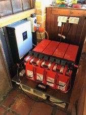
As it turns out, right under the main circuit board I have a large housing which encloses the pool filter and pump at one end (seen in the image in the previous post). This is all under a 2m wide eave on the SE end of the house so very well protected from the elements and sees very little sun (our sun is in the northern sky). The other end of the housing has the spa pump, filter and spa heat pump servicing an in-ground spa but the heat pump was dead and we never used the spa, so I made the executive decision to decommission it and get rid of all the associated equipment to free up the housing for something more useful. It’s perfectly positioned right under the circuit board and is now where I have the battery bank and inverter.

Here’s the inverter and batteries in situ:

IMG_2891.jpeg

The large orange plug is connected to a 20A AC supply outlet with its own dedicated circuit / RCBO on the main circuit board. This provides the grid AC input for the inverter (and this will be a grid side only circuit). I did it this way so I could also supply the inverter from our generator if needed. Unplug from the wall outlet and plug in the generator (I have a spare 20A socket to make up the cable from the generator).

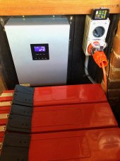
Inverter and battery monitor:

IMG_2892.jpeg

And with the housing lid on it's all discretely hidden away:

IMG_2894.jpeg

This can supply power to the home via the same power inlet previously set up for the generator. I plan to upgrade the power inlet from a 15A (3.45kW) to a 20A inlet (4.6kW) so it can manage the occasional peak loads the inverter is capable of supplying.

Testing
Before installing I had been testing it for a month or so and moved it all from the mancave workbench and into its new home a couple of weeks back. All now in place, tested and working. Batteries are in fine condition and I've done several load tests. I was able to pull 6.7kWh out of them until the first battery hit 10.5V under a 0.2C load, and they all returned to 11.9V after a brief rest. Under actual use I won’t need to take them that far. 50% DOD is equivalent to 6-7 hours of backup. Perfect!

I also tested the UPS function under load and it works great.

Naturally we had a grid outage while I was in the middle of the installation! Figures.

Next steps
Some main circuit board adjustments to be done by a sparky, mostly moving a few designated high power circuits off the backup side of the supply and upgrading the power inlet to a 20A unit as mentioned above (I have the inlet ready). It will be in a permanent state of readiness and this will make the system super simple to use - flip one switch and the backup is active.

It will also mean the off-grid system has the ability (if desired) to provide UPS level backup, which is useful if we are away as power backup can be automatic for Mum in the granny flat. I’ve tested the UPS function under load with the grid power pass through function and it works a treat.

Solar PV:
I’ve been donated 10x 250W Trina panels (yet to pick up) to make up a 2.5kW array. With this particular inverter’s specs I’ll need to put these in a 2S5P arrangement which is an interesting wiring challenge but I think I have that worked out. The array will go on my small flat corrugated metal garage roof. It’s a longish cable run of ~30m to the inverter hence the cabling challenge. I got some used Clenergy rails and mounting feet from my solar installation company for A$100, and via fleabay bought a clamping kit as well as with MC4 connectors, fuses, DC isolator etc.

I’m yet to build the array, this will be part II of the project and should be sometime in the next month or so. So more to update you all with.

Aside from having the solar PV keep the batteries charged instead of using the grid power for that, I’m planning to take the pool pump/filter/chlorinator off-grid. The efficient multispeed pool pump draws about 2-2.5kWh/day depending on the season. I’ve tested the system running from the inverter/battery alone and it works perfectly. Once the solar PV array is feeding the inverter, it will easily handle the pool's energy needs while still having plenty of reserve for covering outages. The battery will pretty much just be providing ballast for the solar.

This will free up about 1MWh/year of my grid tied solar PV energy for other purposes, mostly to be exported to the grid for a little extra export income but it may one day end up being diverted to our hot water system if the off-peak tariff for some reason gets too expensive.

I’ve been repurposing many pre-loved items for this project. The batteries, the solar PV, the rails, the housing and platform and other bits n pieces. The inverter is new, but these new off-grid all-in-one hybrid units are pretty cheap nowadays while being very feature rich.

Budget
All up the budget (inverter, batteries, solar PV, racking, DC & AC cabling, fuses, switches, inlets and outlets, plugs and connectors, conduit and all sundry items) was A$2,400, (~US$1,900). There is going to be some external subsidy bringing it down to A$1,600 (~US$1,250). It is lot less than I paid for the Yamaha inverter generator we've been using for our backup, and that was half the new price. For a 2.5kW array with 6kWh+ useable storage capacity with this feature set I reckon that's not bad going.

As for longevity, who knows?

Now I'm just waiting for an outage! My stats tell me at this time of year it's much less likely.
 
Great project. I grew up in Urunga/Valla, went to high school in Bello.

To feed back into your house, do you just have a lead from the AC output of the inverter and plugged it into the inlet you have installed? Then flick the changeover switch when you get a blackout?

I'd be interested to know what parts of the system you have built yourself versus what you have had to get an electrician to do. Since you mention an external subsidy, I'm assuming it all has to be pretty legitimate and compliant. I'm looking at doing something similar, and while I'm comfortable doing anything not inside my switchboard, I doubt a sparky would touch anything an amateur has put together. How have you dealt with this?
 
To feed back into your house, do you just have a lead from the AC output of the inverter and plugged it into the inlet you have installed? Then flick the changeover switch when you get a blackout?

Yes.

Well, almost.

As it currently stands I do need to turn off a few circuits on the main board before cutting over to backup. I will be getting the sparky adjust those specific circuits so they can never be supplied power when on backup and hence don't need to be touched at all.

Once I have those few circuits adjusted, then it really will be a simple flick of the cutover switch and that's it. Backup power on tap.

These few specific circuits will only be connected to the grid side. If the grid goes down then those specific circuits go offline, and when grid comes back, they come back on irrespective of whether we have backup power supplying the rest of the home's circuits.

This is how I have the oven/stove circuits set up and it works perfectly - I just want that same arrangement extended to some other circuits for idiot proofing. e.g. I don't want our ducted aircon system to attempt to come back on using the backup power supply as it will overload the off-grid supply. And importantly, the dedicated circuit now supplying the off-grid inverter's AC input. I can't accidentally have the off-grid inverter's AC output supplying its own AC input!

I will however need to improve on using just the socket and power inlet arrangement once I want to connect the the pool pump to the off-grid solar PV supply. It might be we have the off-grid inverter's AC output feed a small circuit board and from that I have the power inlet supplied as well as a couple of off-grid GPOs for the pool pump and anything else I might want to run. e.g. the other side of the wall inside the home will become a walk in robe and I'm pretty keen to put in a dehumidifier in that space which could run off-grid as well.

I'll ask the sparky to set that up for me as circuit boards are a bit beyond my comfort zone for the moment.

I don't want to lose the power inlet as it is a fall back option to be able to plug a generator directly to it, should for some reason this system fail.

I'd be interested to know what parts of the system you have built yourself versus what you have had to get an electrician to do.

I had the sparky install the power inlet, change over switch and do the initial circuit board changes. Otherwise the rest is me.

Aside from the other work I mentioned above I'll have them check the switched AC power outlet feeding the inverter's AC input - it's fed by the AC supply cable which was already in situ from a 20A circuit previously dedicated to the old spa heat pump.

Since you mention an external subsidy, I'm assuming it all has to be pretty legitimate and compliant.

The subsidy is a private/personal one, not based any form of govt or other incentive program. It's just the net effect is to bring the cost down by a third.
I grew up in Urunga/Valla, went to high school in Bello.

Then you'd know why I want to get a dehumidifier! How long since you were here last?
 
Yes.

Well, almost.

As it currently stands I do need to turn off a few circuits on the main board before cutting over to backup. I will be getting the sparky adjust those specific circuits so they can never be supplied power when on backup and hence don't need to be touched at all.

Once I have those few circuits adjusted, then it really will be a simple flick of the cutover switch and that's it. Backup power on tap.

These few specific circuits will only be connected to the grid side. If the grid goes down then those specific circuits go offline, and when grid comes back, they come back on irrespective of whether we have backup power supplying the rest of the home's circuits.

This is how I have the oven/stove circuits set up and it works perfectly - I just want that same arrangement extended to some other circuits for idiot proofing. e.g. I don't want our ducted aircon system to attempt to come back on using the backup power supply as it will overload the off-grid supply. And importantly, the dedicated circuit now supplying the off-grid inverter's AC input. I can't accidentally have the off-grid inverter's AC output supplying its own AC input!

I will however need to improve on using just the socket and power inlet arrangement once I want to connect the the pool pump to the off-grid solar PV supply. It might be we have the off-grid inverter's AC output feed a small circuit board and from that I have the power inlet supplied as well as a couple of off-grid GPOs for the pool pump and anything else I might want to run. e.g. the other side of the wall inside the home will become a walk in robe and I'm pretty keen to put in a dehumidifier in that space which could run off-grid as well.

I'll ask the sparky to set that up for me as circuit boards are a bit beyond my comfort zone for the moment.

I don't want to lose the power inlet as it is a fall back option to be able to plug a generator directly to it, should for some reason this system fail.

That all sounds pretty good to me. I like the idea of a separate switch board for the off-grid circuits. I'm tempted to just install totally separate power circuits with wiring and outlets that are really well labelled and visually distinct from everything else. No cutover switch, just totally discrete systems. That way, I don't have to touch the existing wiring in my house, some of which is pretty old and badly installed. I'd just plug appliances into the off-grid power points as appropriate. The only issue would be that lights would stay on grid. No big deal, they use little power and I can live with plug-in lamps during blackouts. Blackouts are rare here, although the voltage is getting ridiculous now that every second house has grid-feed solar (including me).

Then you'd know why I want to get a dehumidifier! How long since you were here last?
I haven't been up that way for a couple of years now. I hear that the trip north of Newcastle is super easy now the highway upgrades are done. It took me an embarrassingly long time to recognise that beach photo, I used to ride my bike there all the time as a teenager, but those stairs are relatively new. I'm on the south coast now, which is a bit like the north coast was 20 years ago. Development is catching up quickly though, and not in good ways.
 
I'm tempted to just install totally separate power circuits with wiring and outlets that are really well labelled and visually distinct from everything else. No cutover switch, just totally discrete systems.
Not so good for us as I have 3 buildings to supply power to and just too many appliances spread around that we'd want to change over to another socket. Even just the fridge is a pain as it requires moving the fridge out to get to the wall outlet. This I discovered while operating with generator and extension cords. Just prefer being able to use everything as it is. But in your case if wiring up alternative circuit outlets where you really need them is easily doable (it'd be a right PITA for us) and outages are infrequent, that makes sense.

although the voltage is getting ridiculous now that every second house has grid-feed solar (including me).
What are you seeing? Being the end of a rural line we can get 30V swings in our voltage and 258+V isn't unusual. The 3.6kW hot water system (overnight controlled load) will see a 10V swing as it cycles on/off. Our Fronius inverter does some high voltage production limiting, it manages it quite well.

I hear that the trip north of Newcastle is super easy now the highway upgrades are done.
Yes the dual carriageway extends from Hexham to the QLD border now. The geotechnical assessment for the Coffs Harbour bypass is underway, expected to be finished in 2024 and will remove the final bottleneck for the highway trip. I believe more funds are about to be allocated to upgrade the section near Taree. It's dual carriageway but not of great standard.
 
What are you seeing? Being the end of a rural line we can get 30V swings in our voltage and 258+V isn't unusual. The 3.6kW hot water system (overnight controlled load) will see a 10V swing as it cycles on/off. Our Fronius inverter does some high voltage production limiting, it manages it quite well.


Yes the dual carriageway extends from Hexham to the QLD border now. The geotechnical assessment for the Coffs Harbour bypass is underway, expected to be finished in 2024 and will remove the final bottleneck for the highway trip. I believe more funds are about to be allocated to upgrade the section near Taree. It's dual carriageway but not of great standard.
It spiked up to 260V yesterday. On sunny days, our inverter tends to shut down at about 9:30am, then oscillate on and off until mid afternoon. This is triggered by sustained voltages above 258V. The standard as I understand it is 216-253V, so I don't get how the supply authority accepts these ranges. I'm obviously a bit annoyed to not be getting much value from the grid connect system, but I also wonder how many appliances will fail prematurely due to excessive voltage. I'm on an old street with old infrastructure, but am pretty close to the centre of town. Apparently the supplier is looking into installing batteries near some of their transformers to smooth things out a bit. Time will tell. It is frustrating how none of this is planned for, and only dealt with reactively, and then only if enough customers (I nearly said consumers) complain. I'm probably the only person on the line who would actually notice the high voltage.
 
It spiked up to 260V yesterday.
That's not good and indicates a definite problem. Most modern inverters can manage the higher voltages we get but 260V is over the top and having an inverter constantly shut down for over voltage is bad.

The standard as I understand it is 216-253V, so I don't get how the supply authority accepts these ranges.
That's the Australian standard range at the grid feed-in point in the National Electricity Market zone (230V +10% / -6% being the supposed standard even though a 240V mean is far more common) although there are small differences between some distribution companies on how the limits are managed within that (and WA is different). Our mean voltage is 245V.

If your voltage readings are at the grid feed-in point then I would be contacting your distributor about it and request they check the voltage supply as 260V even for short periods is out of spec and unacceptable. Not sure if you are in Essential Energy or Endeavour Energy area.

In some cases they can re tap the local transformer to drop the voltage down 5-10V. On rural SWER lines it is harder to do as often they are also looking out for under voltage events at peak evening periods. Another possible option, again depending on what sort of connection your local area has, is if the area is serviced by 3 phase lines, they can perhaps move your connection onto a different phase which may not be suffering the same high peaks.

In some cases the voltage rise happens between the grid feed-in point and the inverter due to inadequate inverter wiring, although for a grid tied system installed by a good solar professional that's not quite as likely. If it were a dodgy bothers set up it's a possibility. My Fronius inverter and meter tell me the voltages at the grid feed-in point and at the inverter, so I can see the difference. In my case it's not much as the inverter is right next to the main circuit board and meters.
 
Update.

Had a sparky in yesterday to do some circuit board mods, so now the cutover to back up power is idiot proof for me and super easy for the wife. No thinking required, just flip one switch and we have backup.

Can also now use the all-in-one inverter's UPS mode if we want.

Two main changes made:

1. Upgraded the power inlet from a 15A to a 20A plug and socket:

IMG_2952.jpeg

I did this as the off-grid inverter's max continuous output is rated at 4kW.
4000W / 230V = 17.4A

2. All the circuits which should be mains power only (3-phase grid tie inverter, ducted AC, oven, induction stove, pool pump) are now restricted to mains power only, plus the dedicated 20A AC circuit supplying the off-grid all-in-one inverter/charger.

This means the all-in-one inverter can now safely operate in pass through UPS mode if we want.

IOW if e.g. we are away while Mum is still home in her granny flat, we can have the cutover switch set to the back up position. The off-grid inverter will simply pass through the AC input to the output and supply all the connected circuits with power as normal. Then if there's a grid outage, the inverter immediately cuts over to battery supply the same as a UPS would.

Meanwhile the mains-only circuits mentioned above would all be off during the outage, and they will all come back on once grid power returns. The off-grid inverter will also automatically switch back from battery power to passing through the grid AC supply.

Because of the change to the AC output plug, I needed to disconnect the old 15A AC output cable from the off-grid inverter and connect the upgraded 20A cable, which meant disconnecting and pulling the battery bank out to access the inverter.

While in there there I also connected up the cable for adding solar PV input later on so I won't need to pull it apart again and also did a little battery cable re routing to make it a little neater.

IMG_2953.jpeg

Still to put up the solar PV, which will be the next step.

In anticipation of that I will also fit an RCD on the off-grid AC output side which can supply an off-grid general power outlet inside the pool pump housing. Once the off-grid solar PV is connected, I can then power the pool pump off-grid.

BTW I've tested the pool pump start up from battery alone and all is good. A video of the test:

 
Next steps done.

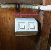
AC output from the all-in-one inverter/charger now feeds a small circuit "board" with over current protection and 2 RCDs. One RCD is for the outage backup supply, the other is for a general power outlet on the other face of the panel the board is screwed on to and which I intend to use to take the pool pump off-grid once I add solar PV to the AIO inverter.

Off grid circuit "board":

IMG_2959.jpeg

Off-grid GPO:
IMG_2960.jpeg

And the 20A plug and socket feeding the home's main circuit board via the manual cutover switch to be used for grid outage backup is already shown in previous post.

This now leaves me with two things to do:

i. I want to redo the terminal connections in the AIO inverter. I plan to either put ferrules on the wire ends, or to fuse them with some solder just so I am certain the connections inside the screw down terminal clamps are very secure*.

ii. Add solar PV! That'll be another adventure to report on.


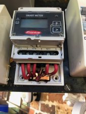
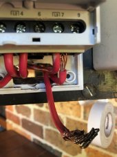
* I had a recent experience with the consumption meter for my grid tied inverter which had a poor terminal connection and as a result it melted the connecting wire's insulation and the meter terminal inside the main circuit board. Glad to have caught it when we did as it was not going to end well. Meter was replaced the other day by the solar installer and connections secured correctly.

IMG_2947.jpeg
IMG_2949.jpeg
 
Next steps done.

AC output from the all-in-one inverter/charger now feeds a small circuit "board" with over current protection and 2 RCDs. One RCD is for the outage backup supply, the other is for a general power outlet on the other face of the panel the board is screwed on to and which I intend to use to take the pool pump off-grid once I add solar PV to the AIO inverter.

Off grid circuit "board":

View attachment 51808

Off-grid GPO:
View attachment 51811

And the 20A plug and socket feeding the home's main circuit board via the manual cutover switch to be used for grid outage backup is already shown in previous post.

This now leaves me with two things to do:

i. I want to redo the terminal connections in the AIO inverter. I plan to either put ferrules on the wire ends, or to fuse them with some solder just so I am certain the connections inside the screw down terminal clamps are very secure*.

ii. Add solar PV! That'll be another adventure to report on.


* I had a recent experience with the consumption meter for my grid tied inverter which had a poor terminal connection and as a result it melted the connecting wire's insulation and the meter terminal inside the main circuit board. Glad to have caught it when we did as it was not going to end well. Meter was replaced the other day by the solar installer and connections secured correctly.

View attachment 51812
View attachment 51813
Yikes!! That could have ended badly! Good catch :)
 
I now have my solar panels.

6 x Longhi 370W panels.
Voc 41.3V
Isc 11.4A

These will be set up as 2S3P, which will nicely suit my inverter's MPPT which has Voc limit of 105V and max current of 50A.

I originally was going to use 10 x 250W Trinas but putting up 6 panels will be easier than 10!

So I pretty much have all I need to complete this project. Except for a bit of time and nice weather!
 
Got to do a little more work today on my off-grid backup power project. Managed to get some rails and 4 panels up. 2 more to go.

IMG_2987.jpeg

Have yet to sort out the wiring and for the cables to feed through some conduit and the roof to connect to a solar combiner box. I have a dektite roof flashing for the roof penetration. I just wanted to get some panels up and see how the rails and clamps work. My first time putting panels up so am learning how this jigsaw puzzle works as I go.

A little fine tuning perhaps with rail placement (was trying to use as many existing batten screw holes as I could) although they are very secure. I'll tidy up the rail ends and as try to get all the panels at the same level so they look nice although you can't actually see them from the ground.

Turns out the pack of rail clamps I have doesn't have enough end clamps so have got another 4 on order, along with some colour coded cables for connecting to the combiner box.

Since I have to wait for those I'll probably move onto the cable routing between where the combiner box will go and the inverter. It's a bit of a run, about 30m. I already have conduit and some 6mm cable for it.
 
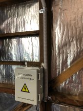
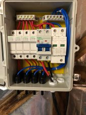
Spent today putting up the conduit for the DC cable run (it's about 30m) and affixed the solar combiner box inside the garage. Did the cable pull as well. I'm using 6mm² cable. Crimped some ferrules onto the end of the DC cable, added a bit of red heat shrink on the positive for easy identification and it's now securely connected to the combiner box.

No pics today.

Tomorrow I'll finish off the conduit and cable run at the inverter end as well as fit the DC isolation switch.

After that it'll be back onto fitting the remaining two panels. Still waiting for my panel end clamps to arrive - parcel tracking says they arrived so I need to look into that. And finally it will be the cabling for the panels.
 
Finished off the conduit run today. Some pics this time:

Combiner box inside garage:

IMG_2993.jpeg

It's a "value" choice box. It all seems in order and the cables are secure.

IMG_2992.jpeg

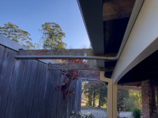
DC conduit run exiting garage:
IMG_2994.jpeg

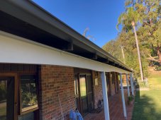
and then all along the facia board to other end of house:
IMG_2995.jpeg

Conduit will be getting painted to match the facia. But I think I've made a rookie error - I just realised I haven't allowed for expansion joints... The far end exits into some flexi conduit, perhaps that will be enough but I'll have to see how it fares come Summer heat. If I notice some conduit bending I'll retro fit some expansion joints.

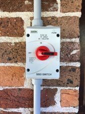
And near the inverter housing I have a DC isolator switch which is on the wall under the 2m wide eave:
IMG_2996.jpeg

And from there the conduit extends to the inverter inside its housing.

While it's already connected to the inverter, I want to redo the terminal connections but not today. I have to disconnect and move the battery bank to do that and it's a bit of an awkward job. With other work I needed to do, this was enough.

I have my extra solar panel rail clamps now so the the last 2 panels can go up when I'm ready. I think I'll put the rails up but leave fitting those 2 panels until last as I need to work out my cable management for the 4 panels which are already in situ. Still waiting for my PV cable extensions to arrive, which are due to arrive in next couple of days.

Once I have those then I can finish off this job, switch on the panels and fingers crossed I haven't screwed anything up. I'll do a few multimeter checks on voltage polarity just to be sure.
 
MY PV cables arrived so it was time to started wiring these puppies in.

Didn't grab any photos today. Might get some tomorrow to post.

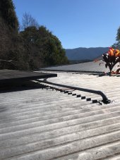
I drilled the roof penetration hole and affixed the dektite, pushed through a conduit elbow and got all the cables pulled through the conduit flex inside the garage and down to the combiner box, and then ran them through straight conduit along the garage roof with exit holes in the conduit for wires to connect to each pair of panels along the array.

After that it was connecting the first two panels in series, adding the MC4 connectors to the extension cable ends and connecting the first two panels. Then back at the combiner box I needed to work out which two of the three pairs of wires were from the connected panels. Simple multimeter voltage check told me which two were the right ones and so plugged them into position #1 in the combiner box.

Time to test if the inverter would recognise the panels were online and whether there would be any charge current flowing.

Before doing that I did a polarity check just to be sure. All good.

Turn off the grid power supply to the AIO inverter, turn off the inverter and then flip the solar DC isolator switch to on. Re power up the inverter and fingers crossed nothing starts smoking. All good, inverter starts up and after a while it recognised the solar panels were connected and a small current began flowing into the batteries. It was late afternoon by then, the panels were shaded and the batteries were already at float level charge so I wasn't expecting much in the way of production. But there was voltage (~70 something volts) and about 35W was flowing into the batteries, so about 0.5A.

It took most of the day and I'm pretty knackered. So much up and down the ladder and up and down to/from the roof. As an amputee with a prosthetic leg it takes longer to do most things and I need to take extra care. But I sure have an extra appreciation for professional solar installers who do this stuff day in day out. Obviously my efficiency is very low as every step of the way is my first time doing it. but I'm getting there.

Still plenty to do.

I have to connect the other two panels already on the roof. Then make up two more rails for the final two panels to be fitted and installed and connect those as well.
 
Great work. I saw current flowing into my battery for the first time only a couple of days ago, it's a good feeling. I have only installed half of my planned 12 panels on the roof so far and am with you on low efficiency. The pro's certainly get the job done quickly, but I think we amateurs can have an edge on quality, since we can be careful and take our time with things.
 
I tested the system operation today by hooking up the pool pump to see if the solar PV would run the pump. It does. :)
Did a little video of it:


Part way through the video I noted the solar PV voltage was 51V with a PV output of 420W while the display said only 1A, and I thought that wasn't right. Since then I realised the 1A reading was just for current flowing into the battery, not total current from the solar PV. The balance of course was being used to supply the output loads.

The two panels only (Pmax rating of 740W) were supplying ~420W and I saw 422W at one point. The panels are flat (2 degree slope away from the sun) and this is Winter sun at about 11:30am. At that time the sun's altitude was 40.7 degrees and so the angle of solar incidence would be 90+2-40.7 = 51.3 degrees. Cosine(51.3 deg) = 0.625 or I should expect about 62.5% of output.

62.5% * (2 * 370W) = 462W. So I was getting 422W/462W = 91.3% of theoretical panel output under STC conditions. Considering the cable losses, panel temps would probably be above STC, and I didn't quite have a full load running I reckon that's excellent.

I did also test it briefly with the pump running on its start up cycle, which draws about 920W. The MPPT was still supplying about the same power output so I don't think there was a load constraint.

That's was just 2 of 6 panels supplying power, so pretty confident the full array will be more than able to keep my pump happily running off grid. Test will be cloudy/rainy days to see how it goes.

Decided not to do any more work on the array today, although I may connect the other two panels later this afternoon if I feel up for it. Still a bit sore from yesterday's efforts and I had a cycling session at the local velodrome this morning as well.

IMG_3011.jpeg

Took a quick pic by reaching up to show the conduit and roof penetration/dektite. This will also be covered over when the final two panels go up.
 
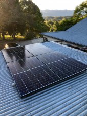
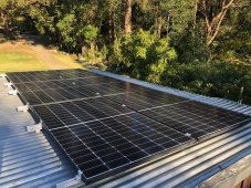
Finished off installing the PV array today, 2.22kWp:

IMG_3032.jpeg

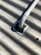
Better pic of the roof penetration/dektite, which is now hidden underneath the panels:

IMG_3021.jpeg

And all connected up and supplying power:

IMG_3016.jpeg

By the time I'd finished it was late afternoon so again low sun and some shading, plus the battery is just getting a float charge while the pool pump ran from the off-grid system all day.

Pretty happy with how its all turned out for my first ever DIY solar/battery project. Bit buggered now!

I still have a few small things to do. I want to redo the terminal connections into the AIO inverter (fit some ferrules), and I think I could use a better quality battery DC isolator and fuse arrangement than the one I have so need to look into that. And paint the conduit run to match the facia board.

This system will be capable of supplying quite a bit of energy I can't really use. Aside from the pool pump I don't have much of a load to give it. One future idea is a dehumidifier which can run in a yet to be constructed walk-in-robe which will be on the other side of the exterior wall from where the battery/inverter and circuit board are located. So an off-grid power outlet could easily be added for that.
 

diy solar

diy solar
Back
Top