diy solar

diy solar

Basic wiring connection to/ from inverter

dawgleader1

New Member
Joined
Mar 9, 2020
Messages
19
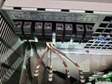
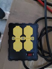
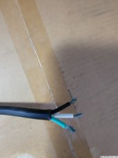
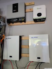
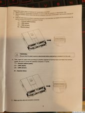
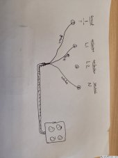
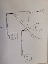
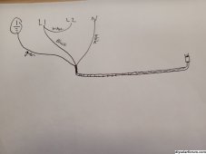
Hey guys & gals. I have a very basic, stupid question I hope I'm not drummed out of here for. I have a MPP solar 6048 inverter, I originally had a Growatt 3000tl but decided that I wanted/ needed something bigger so please ignore that in the picture, I won't be connecting that. I will be completely off-grid with this system, not connected directly to the grid or my home's system, I'm using it purely as an emergency/ back-up power system for storms, and of course the zombie apocalypse. I'd like to connect a power cord to the AC input so that I can plug this into one of my home's regular AC electric plugs in the garage. This will allow me to charge up the batteries and keep them topped off in the case of a power loss. Once the batteries are full, I'll unplug it and re-plug it as needed to keep the batteries full but I won't be leaving it plugged in 24/7 after I'm charged up. Then I'd like to connect a power cord/ surge protector outlet to the AC out on the inverter to plug in my things, such as my freezers and such when needed. I also have a 12 panel, 4000w solar panel array but I'm not ready to connect that yet. The panels have been mounted but I haven't connected any wiring yet so that will be a project for later. I just want to get the batteries and inverter set up so that I'm ready for the upcoming winter, so we're not shit out of luck with an ice storm. The 6048 inverter is connected to 2x all-in-one 10kwh/ 48v battery packs for 20kwh storage. My problem is the power cords for AC outlet connection in and AC surge protector out are 3-wires and the AC input and output is 4 connections. I know it probably sounds like I'm a moron but what's my play here? Do I just connect the 3 to 3 and leave 1 empty? Also, as a side question, in this scenario, since the house outlet is grounded, I won't need to ground the inverter/ batteries again, correct? I've attached a few pictures of what I'm dealing with. Any advice is greatly appreciated. I can also take criticism if I'm completely crazy or something is way off. I'm looking forward to hearing from anyone willing to help. Thanks in advance.
 

Attachments

  • 20231019_152053.jpg
    20231019_152053.jpg
    1.3 MB · Views: 13
  • 20231019_152319.jpg
    20231019_152319.jpg
    638.8 KB · Views: 14
  • 20231019_152223.jpg
    20231019_152223.jpg
    565.4 KB · Views: 12
  • 20231019_161811.jpg
    20231019_161811.jpg
    624.9 KB · Views: 11
  • 20231019_161741.jpg
    20231019_161741.jpg
    654.3 KB · Views: 14
So what you're looking at is a 240v split phase inverter and single phase 120v cords. You see the ports labeled L1 and L2? Each of those to the N port will give you the 120v your power strip is looking for. If you wanted to put in more power strips you could use the other L terminal as well, so L1 + N = 120v and L2 + N = 120v, but L1 + L2 = 240v!

On the input side that inverter is going to look for a 240v split phase input as well to charge. Will found this out when he first reviewed the predecessor the LV5048 and figured out the charging issue at about 7:15 into the video and a workaround. If you're going to be charging it from a wall outlet on an extension cord you'll need to do the same thing he did.


So for your input you can use L1 + N and a jumper from L1 to L2, and on the output use EITHER of the L1 + N or the L2 + N to feed your power strips.
 
You could possibly get one of those generator cords that plugs into say 30A 240v and has multiple 120v pigtails and remove the 240v end and use it as your power cord coming out of the inverter as it wil have L1 and L2 hot wires.
 
Hey Redneck, thanks so much for chiming in with some advice. You seem to explain the reasoning and the how-to pretty well, even for someone like me. I think I understand what you're saying but just to be on the safe side, if you don't mind, I'm going to regurgitate it back to you in my own words so I can visualize it before I try it, mess it up, and destroy my inverter, or burn my house down, or kill myself...

So, if I'm understanding you, for the output, I would take that stripped 3-wire extension cord and connect the wires to ground-green (the symbol on the left)/ L1- black/ N- white, leaving the L2 spot completely empty. That would give me the 120v output I need for the 4-outlet surge protector. And the inverter would recognize that I only need that much power out, not the full 240? The other option you said, which I don't see that I would need to at this point but, IF I WANTED TO, I could do the same thing and connect a 2nd extension cord to ground (same symbol on the left)/ L2/ same N and that would give me an additional run of outlets. In that scenario, I'd have 2 wires going into the ground and N spots, one from each 3-wire extension cord, wrapped together into the same connection and only 1 wire into each of the L1 & L2, the L1 & L2 not overlapping/ connected, one wire from each extension cord. Is that correct?

As far as the input is concerned, I watched the video you provided, and it gives me an idea, but Will didn't show himself actually connecting the wiring or the bridge. So just to clarify, I would connect the 3-wire stripped extension cord to the ground-green (the symbol on the left)/ L1-black/ N-white. And then a single wire for the bridge, only running from the L1 to L2. Would just any wire work? Or does it need to be a specific wire to bridge properly or of a certain gauge to handle the current? So in this scenario, I'd have 1 wire in the ground and N from the stripped extension cord, 2 wires in the L1 (1 from the extension cord and 1 from the bridge), and 1 wire in the L2 from the bridge. Is that correct? With this being the case, will the inverter draw power properly to charge the batteries since it's looking for a 240v and only getting a 120v?

I've attached a couple roughly draw pictures to clarify what I'm explaining above. So assuming I'm correct with this, what dangers should I be aware of? Anything that would pose a safety hazard as long as the wires are connected correctly and tightly?

Once again, I greatly appreciate your help and expertise.
 

Attachments

  • 20231103_164300.jpg
    20231103_164300.jpg
    466.5 KB · Views: 5
  • 20231103_164305.jpg
    20231103_164305.jpg
    440.4 KB · Views: 6
  • 20231103_165541.jpg
    20231103_165541.jpg
    681 KB · Views: 6
Hi Balrog, thank you for jumping in on the thread. Looking at what you suggested, you're talking about one of the plugs like what I attached below? It seems to handle the full 240v and it offers the correct 4-wire cord so connection is straight forward. Is there any benefit in performance or safety that this would provide over my original plan with the 3-wire connected following the plan like Redneck suggested? I kinda like the idea as presented by Redneck since it allows for a second extension cord/ outlet box to be attached if I decide I need more outlets later. But, if it would be better or safer for some reason to use the 240v/ 4-wire plug then I can go that route. Thanks for the help on this!
 

Attachments

  • plug.PNG
    plug.PNG
    150.6 KB · Views: 1
  • wire.PNG
    wire.PNG
    98.6 KB · Views: 1
Yup, you're understanding correctly. As for the wire size, being as that it's going to be able to put out more power than your outlets are rated for (30-ish amps to feed 20a outlets), anything over 12awg wire would be excessive.
 
Yup, you're understanding correctly. As for the wire size, being as that it's going to be able to put out more power than your outlets are rated for (30-ish amps to feed 20a outlets), anything over 12awg wire would be excessive.
Yes, additionally OP asked about additional outlets for future. While I see the practicality of this there is a limit to how many cords/plugs you can safely daisy chain together off his inverter based on the first line connection. This is all temporary off grid SHTF/grid down emergency type stuff so some caution is needed as the safeguards of code built are not available, but some trial and error may yield additional flexibility. Just be safe and test.
 
Ok guys, Thanks so very much for your help and assistance. I pretty confident in what you've explained. So I'm going to give it a run in the next week or two. If I don't kill myself, I'll try to give you an update.
 
If it were me, i would wire in an L14-30R and use a cord as mentioned above with all 4 wires.
Plenty of breakout cords for temp shtf use available.
 

Attachments

  • Screenshot_20231107_134405_Chrome.jpg
    Screenshot_20231107_134405_Chrome.jpg
    209.7 KB · Views: 3
Back
Top