diy solar

diy solar

Battery Options with Existing Grid Tied System.

ABHockey

New Member
Joined
Jul 17, 2024
Messages
5
Location
Texas
I currently have a 7.65 kw Solar Panel system consisting of (18) 425 W SunPower Panels. It's Tied to the Grid and I have NET metering. I'm not in California and I have about 103% offset using ~10-11000kwh a year. I still have an electric bill, but it's low and based on Wholesale Resale pricing.

I'm looking at adding a battery system to this current setup. I got a quote from my Solar Installer for the Tesla PowerWall 3 and it came back to 16k.
For that price I've looking into DIYing it and have looked at the Bluetti EP900+B500 and the EG12KPV/ Solark12k with Server Rack Batteries.

I like the idea of the hybrid invertors because I'm already selling excess energy. My biggest sense of confusion is how to install the invertors. The videos I've watched plug in the Solar to the Invertor, but because my solar is already plugged in do I just need to wire the invertor to the main breaker and then to the battery system?

Thanks for any help!
 
What sort of inverter do you have - it might limit your options - Tesla, Enphase, and a few others are proprietary and only work with their equipment.
 
The technical term is AC Coupling. The wiring and set up of such a system is dependent on where the existing grid-tie system connects, either in the main panel or ideally in a subpanel if there is one.
Most existing grid-tie systems are connected via an added breaker in the main panel. This means that either a new critical loads subpanel must be installed or the connection between the electric meter and main breaker has to be intercepted and the new hybrid battery inverter is inserted in the circuit. A Tesla powewall has slightly different wiring but still needs a gateway installed between the meter and main breaker.
The up side is this provides whole house back-up but the system then has to be large enough (expensive) to operate everything in the house, not all at once but is usually larger than only trying to power a critical loads subpanel.
Thank you! Current system is connected to main breaker box.
 
Solar Battery Options.png


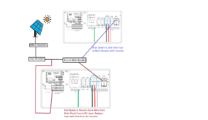
Here's a mock up drawing of what I'm trying to figure out the answer is with the EG4 12kpV Invertor Diagram in their wiring connections guide.

If I run just the straight blue option for some reason I keep thinking that the invertor will not communicate with the panels.
 
Option A would only work if the Enphase microinverters were disconnected and DC from the panels was fed to the PV inputs. This isn't necessary.
AC from the microinverters can be connected to the gen terminals and would flow upstream to the main panel via the Grid connection. The problem with both options as shown, there is nothing connected to the Inverter Load terminals. In a grid outage the inverter disconnects from the Grid input so there is no connection to the main panel where all the loads are and the inverter is useless.

You rock! This makes so much more sense. I was thinking the PV input deals in DC vs the output that would be AC coming from the micro Inverters.

With the Solar inputed to the GEN terminals and then connected to the main breaker via the GRID terminals the issue still remains with the LOAD terminals not being utilized correct? In this case I would require either a SubPanel / Critical Load correct?

Solar to GEN, Main Panel to Grid, SubPanel/Critical Load to Load.

Most existing grid-tie systems are connected via an added breaker in the main panel. This means that either a new critical loads subpanel must be installed or the connection between the electric meter and main breaker has to be intercepted and the new hybrid battery inverter is inserted in the circuit
This makes more sense now to me. I had to draw it out to fully appreciate what I was looking at. Thank you again!

The manual also makes small mention of this
The 12kPV can also utilize AC-coupled solar input through the GEN port in purely off-grid systems.
But the part that confuses me there is it I don't want it to be purely off Grid. I'm guessing it's trying to say I can't have the invertor have backup Generator capabilities in the grid because the back up generator would plug into the Grid area instead.
 
Last edited:

diy solar

diy solar
Back
Top