diy solar

diy solar

Battery set up for RV solar system

ButcherCarl

New Member
Joined
Jan 22, 2024
Messages
21
Location
Indiana
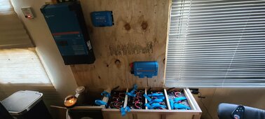
Im setting up a 12V solar system for my RV.
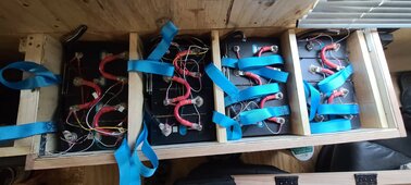
I have 4 separate batteries with a BMS on each battery.
Victron Multiplus II 12v 3000VA 120A
Im asking if I can attach each battery separately to the Lynx Distributor, or do I have to wire all the batteries in series, basically making one big battery, and attaching the one big battery to the Lynk Distributor?
I want to attach them all separately. My BMSs are all JBD 4s. 2 of them are 150A and 2 of them are 200A.
The batteries are, 2 of them are 304Ah, and 2 of them are 302Ah.
Can you make one big battery with 4 separate BMSs, or would I have to buy a new BMS that is 16s?
Im confused because, if you get say 4 100Ah battle borns, they would all have their own separate BMS, and you wire them all in series, right? So you should be able to do it with 4 separate DIY batteries, correct?
This isnt all of the system, Im just laying it all out, figuring out where I want to put the Cerbo GX, the Shunt, etc, and the display.
I want to get the batteries figured out, before I go any further figuring out where I want the rest of the components.
 

Attachments

  • 20240310_160903.jpg
    20240310_160903.jpg
    279.6 KB · Views: 11
  • 20240310_160911.jpg
    20240310_160911.jpg
    273.8 KB · Views: 9
12v battery and 12v inverter. You can connect each battery separately to the lynx.

12v is 4s. 16s is for 48v battery.
Yes, I dont know why I asked about 16s. Thats a little embarrassing.
So, I should run each battery to the Lynx individually, instead of wiring them all in parallel, and then to the Lynx?
Which is more efficient for the batteries?
I would think wiring them all in parallel, would give me better capacity for the system, then running each individual battery separately to the Lynx. Is this correct, or will the system perform the same either way?
Batteries to bus Bar(lynx) with equal length wires is the ideal set up. Better current sharing ability and will give you the option to match fuses to your two different BMS outputs.
 
Batteries to bus Bar(lynx) with equal length wires is the ideal set up. Better current sharing ability and will give you the option to match fuses to your two different BMS outputs.
So dont parallel the batteries?
Just wire each battery separately to the distributor individually?
Thats how I was going to do it to begin with, but all the schematics I have seen, parallel the batteries together and then run the wires to the distributor.
 
This is ideal…

On a Victron PowerIn (with fuses added - see YouTube) connect each battery with equal length and size wires. Then the negative side goes to a shunt (Smartshunt or BMV712) and then to a Victron Distributor (or another PowerIn with fuses). And the positive goes to a on/off switch and then to the “Load” Distributor . All loads and chargers get attached to the Load Distributor.

It sounds like you are doing something like that.
Youve got me confused.
What are you talking about, referring to the "Victron PowerIn"? Are you talking about the Lynx distributor, or the Inverter?
The way you are describing the batteries, is to parallel them, prior to hooking them up to the Lynx distributor.
I am wanting to connect each battery to the Lynx, individually, then connect the negative from the Lynx, to the Shunt, and the power from the Lynx, goes to an On/Off switch, then, to the inverter.
 
The Victron architecture wants you to use the power in as a bus bar for battery connection. The distributor is for output and is fused. Both pieces are the same with the power in does not have led's to show blown fuses a bit of hardware and the fuses that the hardware is needed for. I would suggest searching utube there are easy mods that can be done to fit you needs.
 
Diagram, the VE shunt is optional, you can fit the smart shunt in its place.
View attachment 201438
It looks like the way I had planned it out, is exactly the same as this schematic, Im just using the Distributor as the in, and the out. I dont see the need for the power in. The batteries can go into the distributor, they are fused, then the negative bus goes to a shunt, then to a system fuse, then to the inverter. The pos goes to battery shut off switch, then to inverter.
This isnt a stand alone house system, Its for a Travel Trailer.
The inverter feeds into the circuit breaker box/12v load distribution, powering the camper. It doesnt seem that there is a need for the Power In.
Am I wrong about that?
Here is a example of a modded power in that is going into my RV.
I decided sense I would not be pulling large amps ( Likely biggest draw 35 amps for 12 minutes. ) there was no need to parallel each battery to the power in. It was cheaper to purchase the power in add fuses and hardware and in the entrust of less connections installed the on/off battery switch and the smart shunt directly to the power in. This made it compact ( As I have limited room ) On the other side of the power in is a Victron MPPT 100/30 and a 75/15 along with breaker.
Yes, this is how I had planned mine out.
How is the system working for you?
 
Yes, this is how I had planned mine out.
How is the system working for you?
I will let you know when I am done. The Victron 12/1200VA will be here tomorrow. I am ordering a Victron 30 Amp smart charger tonight. I'm very impressed at how adjustable and the " everything " works together aspect of this equipment.
 
Back
Top